Modems

a modem and optical fiber technology, applied in the field of modems, can solve the problems of major problems to be overcome, the cost of continuing optical fibre to each well head, and the difficulty of achieving the effect of large distance differences between modems

Inactive Publication Date: 2005-11-03
VETCO GRAY CONTROLS
View PDF19 Cites 23 Cited by
  • Summary
  • Abstract
  • Description
  • Claims
  • Application Information

AI Technical Summary

Benefits of technology

[0017] Examples of the present invention can provide a copper wire modem that is able to transceive over distances up to about 40 km (depending on cable type) with a data rate of up to about 115K bits per second, and communicate via a single power cable in a multidrop configuration with large differences of distance between modems.

Problems solved by technology

Although fibre optic technology is able to meet such needs, the continuation of optical fibres to each well head is expensive.
However, there are two major problems to be overcome.
Firstly, the development of fluid and / or gas extraction systems has resulted in more offset well heads from the CDU and at greater distances.
The second problem is that if the communication is via the power cable, then to avoid additional wires the modem system has to be multidrop, as opposed to less efficient point to point systems.
For subsea applications involving wells offset from the CDU however, the difference in the distances between modems is substantial.
This will result in the signal level at a slave modem at the CDU, only 5 km away from the master modem, totally swamping the modem input, i.e. the signal level will be well above the dynamic range of its input.
Thus, although the prior art modems can operate in multidrop mode they are unable to handle a large variation of distance between them.
However, these modem designs are not capable of operating under these more severe conditions in a multidrop system arrangement with large variations of distance between modems and where long offsets are required.

Method used


Image

  • Modems
  • Modems
  • Modems

Examples


Embodiment Construction

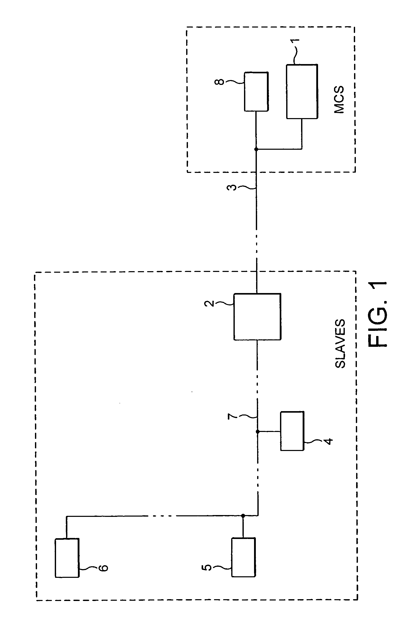
[0021]FIG. 1 shows a typical communications arrangement between a Master Control Station (MCS) and a complex of fluid extraction subsea wells, serviced by a Central Distribution Unit (CDU) 2. Electric power is transmitted from a power source 1 located at the MCS to the CDU2 via an umbilical 3, and is continued to offset wells 4, 5 and 6 via an umbilical 7. (Note that three offset wells are shown by way of example only, but such an arrangement could accommodate in excess of two hundred and fifty slave modems at various offsets communicating via DC or AC power systems.)

[0022] At the MCS, a single master modem 8, as stated above, can host in excess of two hundred and fifty slaves, and is connected to the power line passing through the umbilical 3 and on through the umbilical 7. By using programmable message preambles, multiple master modems can operate down the same umbilical on separate conductors without suffering destructive crosstalk. Each modem has a two wire interface and can be...


PUM


Abstract

A modem for receiving and transmitting data from and to a conductor comprises an output drive for transmitting data to the conductor, a receiver for receiving data from the conductor and impedance matching means for matching the impedance of the receiver input with the impedance of the conductor, wherein the gain of the output drive, the receiver gain and the impedance of the receiver input are all adjustable.

Description

CROSS-REFERENCE TO RELATED APPLICATION [0001] This application claims the benefit of United Kingdom Patent Application No. 0409862.0, filed on May 1, 2004, which hereby is incorporated by reference in its entirety. TECHNICAL FIELD OF THE INVENTION [0002] This invention concerns a modem suitable for use in a multidrop configuration. BACKGROUND OF THE INVENTION [0003] Underwater fluid or gas extraction systems, for example subsea oil extraction installations, typically include a Master Control Station (MCS) which is often located on the shore and underwater well head complexes. Communication between the MCS and the well heads is typically effected by the use of fibre optic technology, for example as described in GB 2 396 086 and U.S. patent application Ser. No. 10 / 726,674. The fibre optic cables are generally incorporated into the cables or umbilicals interfacing the two sites and these distances can typically be in excess of 40 km. There is a current trend for the need for communicat...

Claims


Application Information

Patent Timeline
Patent Type & Authority Applications(United States)
IPC IPC(8): H04B3/56H04LH04L25/12H04M11/00H04M11/06
CPCH04M11/066H04B3/56H04B3/58
Inventor CAUSIER, STEPHEN JAMES
Owner VETCO GRAY CONTROLS
Why Eureka
Try Eureka