
Perpendicular magnetic recording medium, manufacturing process of the same, and magnetic recording/reproducing apparatus using the same

a technology of magnetic recording medium and manufacturing process, which is applied in the direction of magnetic field orientation, record information storage, instruments, etc., can solve the problems of not suppressing the spike noise caused by the domain wall, methods cannot solve the above problems, and observe the spike noise, etc., to achieve excellent fly ability of the recording head, suppress the spike noise and amplitude modulation of output signals, and high reliability and stability

Active Publication Date: 2005-11-03
WESTERN DIGITAL TECH INC
View PDF17 Cites 35 Cited by
  • Summary
  • Abstract
  • Description
  • Claims
  • Application Information

AI Technical Summary

Benefits of technology

[0009] Under such circumstances, it is a feature of the present invention to provide a perpendicular magnetic recording medium capable of suppressing the decay of magnetization in recorded magnetization caused by reproducing output fluctuation and stray magnetic fields to improve the surface flatness of the soft magnetic underlayer and realize excellent fly ability of the recording head and a high medium S / N ratio at 7.75 gigabits per square centimeter. It is another feature of the present invention to provide a highly reliable high density magnetic recording / reproducing apparatus that uses the medium.
[0011] In the above medium, the magnetization of the soft magnetic underlayer is controlled and the underlayer is formed on an amorphous layer or nano-crystalline layer, thereby suppressing the decay of magnetization in recorded magnetization to be caused by the output signal fluctuation and the stray field so as to improve the fly ability of the recording head.
[0013] According to the present invention, therefore, it is possible to realize a perpendicular magnetic recording medium capable of suppressing both spike noise and amplitude modulation of output signals, as well as the decay of recorded magnetization to be caused by stray fields, and realizing excellent fly ability of the recording head. In addition, it is possible to realize a highly reliable and stable magnetic recording / reproducing apparatus having a low error rate at 7.75 gigabits or over per square centimeter.

Problems solved by technology

However, the method for providing the hard magnetic pinning layer might cause a problem; a magnetic domain is easily formed at the inner and outer edges of the subject disk respectively and spike noise is observed around those edges.
On the other hand, the method for using the anti-ferromagnetic layer to suppress the domain wall motion of the soft magnetic layer is effective to suppress the decay of magnetization to be caused by the domain wall motion in the recorded magnetization, but it might not suppress the spike noise to be caused by the domain wall.
Any of those methods cannot solve the above problems that obstruct achievement of the surface smoothness of the soft magnetic underlayer, the fly ability of the recording head, etc.

Method used


Image

  • Perpendicular magnetic recording medium, manufacturing process of the same, and magnetic recording/reproducing apparatus using the same
  • Perpendicular magnetic recording medium, manufacturing process of the same, and magnetic recording/reproducing apparatus using the same
  • Perpendicular magnetic recording medium, manufacturing process of the same, and magnetic recording/reproducing apparatus using the same

Examples


first embodiment

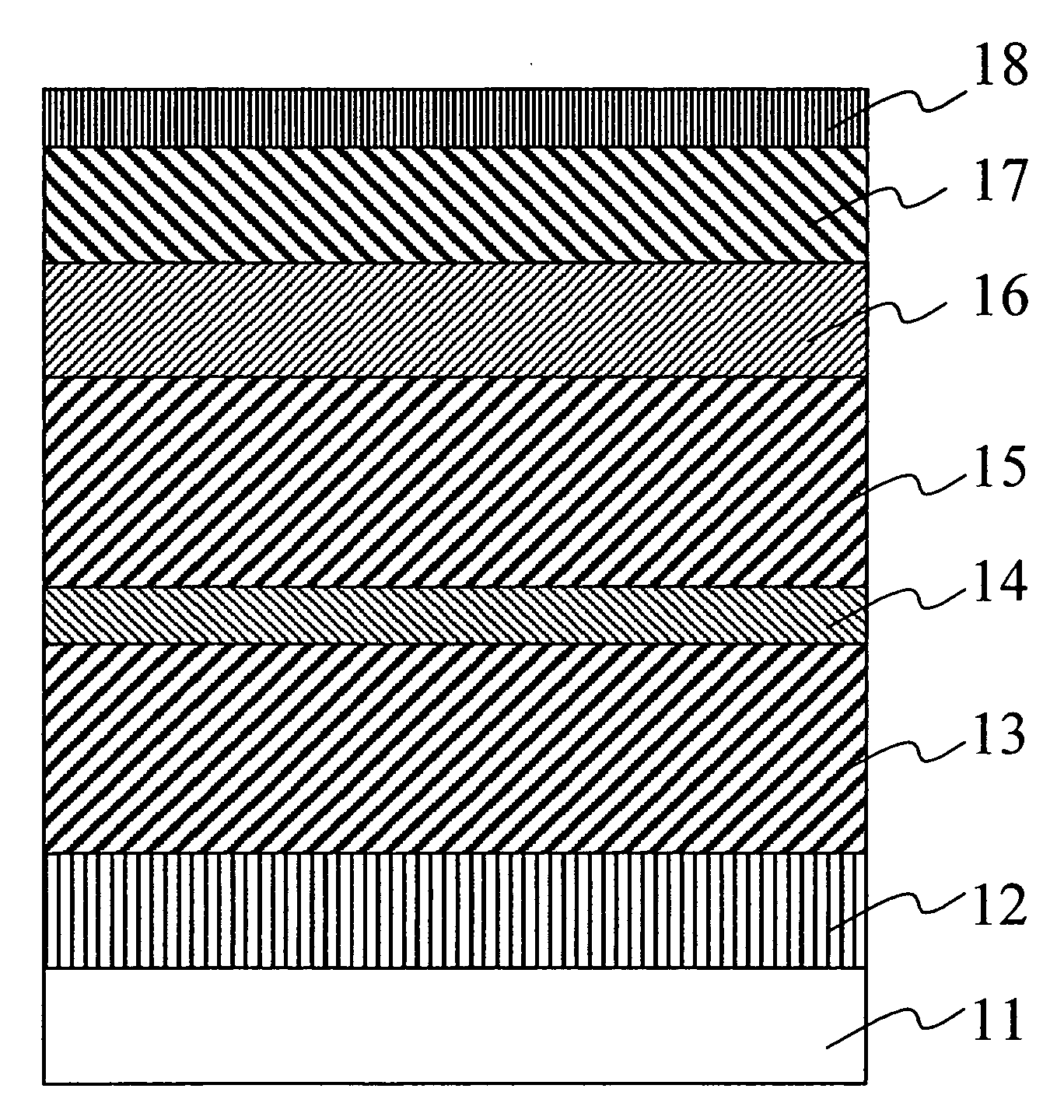
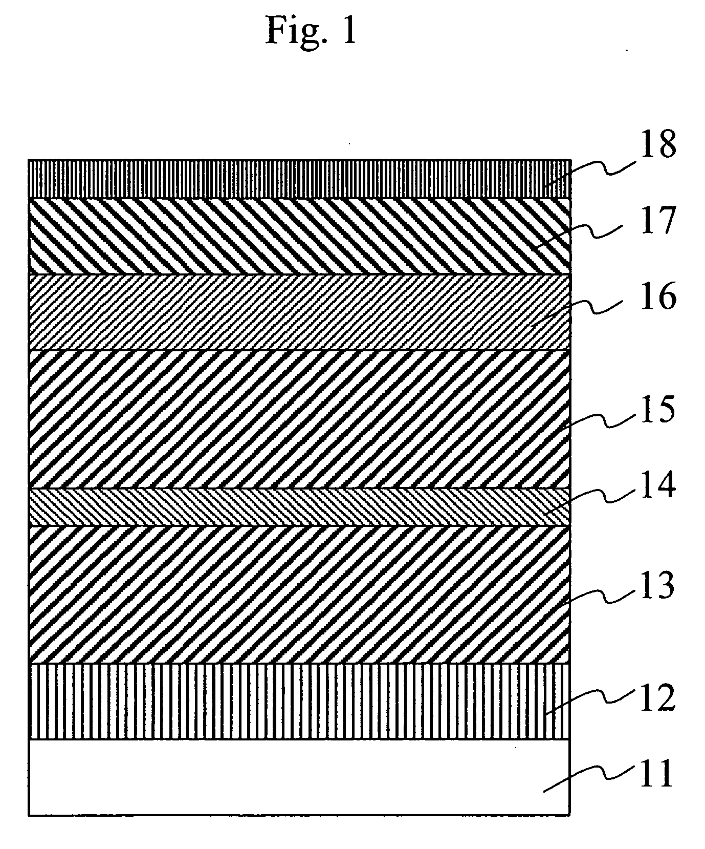
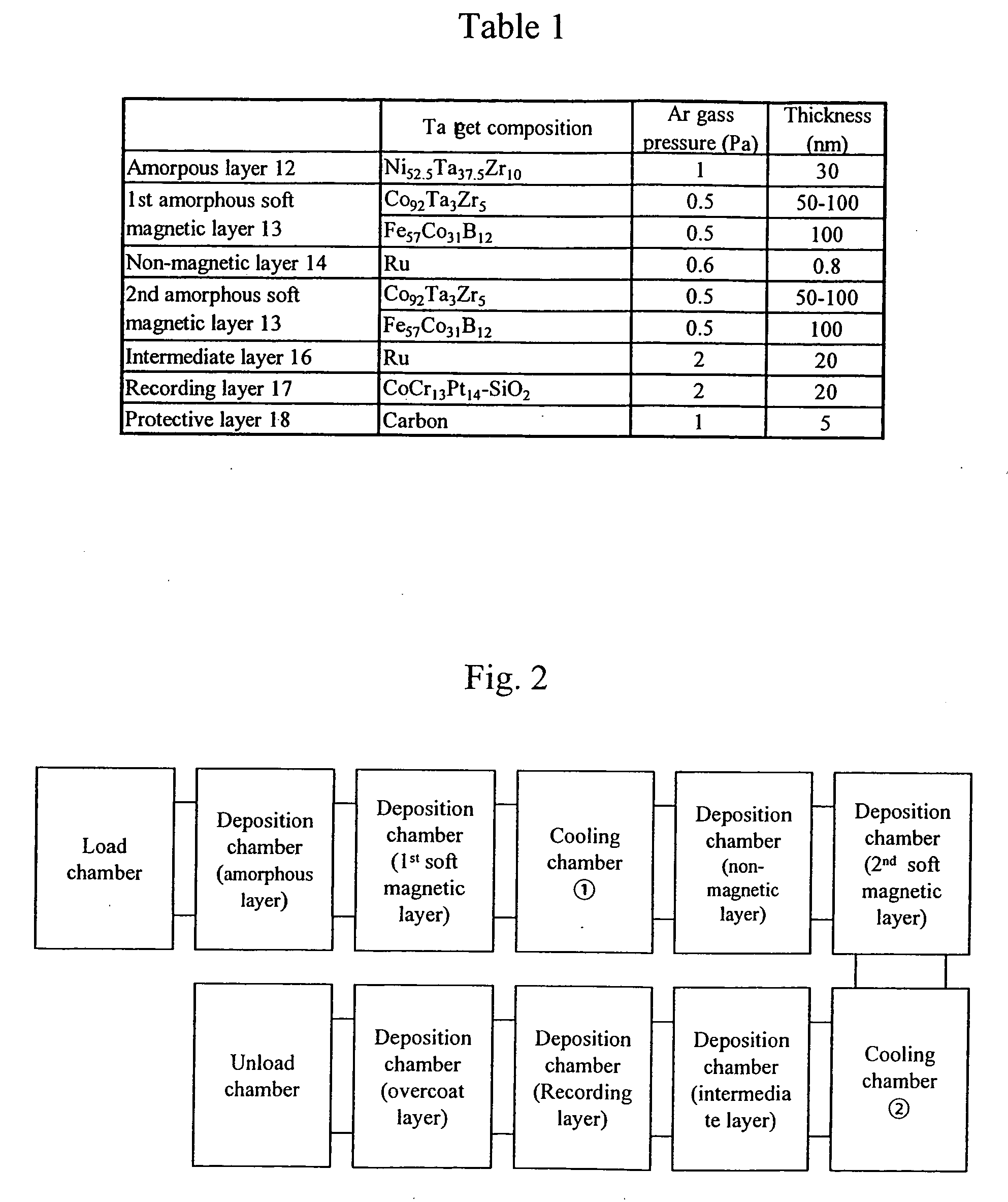
[0065]FIG. 1 shows a structure of a perpendicular magnetic recording medium in this first embodiment. On a 2.5-inch glass disk substrate 11 were formed an amorphous layer 12, a first amorphous soft magnetic layer 13, a nonmagnetic layer 14, a second amorphous soft magnetic layer 15, an intermediate layer 16, a perpendicular recording layer 17, and a protective layer 18 successively with use of a sputtering method. Table 1 shows the target, the Ar gas pressure, and the film thickness of each layer of the medium.

TABLE 1Ar gasFilmTarget compositionpressure (Pa)thickness (nm)Amorphous layer 12Ni52.5Ta37.5Zr10130First amorphous softCo92Ta3Zr50.550-100magnetic layer 13Fe57Co31B120.5100Nonmagnetic layerRu0.60.814Second amorphousCo92Ta3Zr50.550-100softFe57Co31B120.5100magnetic layer 15Intermediate layerRu22016Perpendicular CoCr13Pt14—SiO2220recording layer 17Protective layer 18Carbon15

[0066] At first, NiTaZr to form the amorphous layer 12 and CoTaZr or FeCoB to form the first amorphous so...

second embodiment

[0090] In this second embodiment, a description will be made for a result of checking a relationship between the cooling timing and the antiferromagnetic coupling magnetic field magnitude Hex that works between the first and second amorphous soft magnetic layers using a medium manufactured just as the medium A in the first embodiment.

[0091]FIG. 10 shows a schematic block diagram of deposition processes for manufacturing the media used in this second embodiment and comparative examples.

[0092] The deposition process (1) is a process for manufacturing the medium A used in this second embodiment. A cooling process is provided between a process for forming the first amorphous soft magnetic layer 14 and a process for forming the nonmagnetic layer 14.

[0093] The deposition process (2) for manufacturing the medium in the comparative example includes a cooling process provided between the process for forming the nonmagnetic layer 14 and the process for forming the second amorphous soft mag...

third embodiment

[0105]FIG. 13 shows a layer configuration of a perpendicular magnetic recording medium in this third embodiment. On a 2.5 type glass substrate 130 were formed an amorphous layer 131, a first amorphous soft magnetic layer 132, a first ferromagnetic layer 133, a nonmagnetic layer 134, a second ferromagnetic layer 135, and a second amorphous soft magnetic layer 136 successively with use of the sputtering method. The medium was then cooled down to about 100° C. in the magnetic field. After that, an intermediate layer 137, a perpendicular recording layer 138, and a protective layer 139 were formed successively on the substrate 130.

[0106] While the medium was cooled, the magnetic field was oriented from outer periphery to inner periphery in the radial direction of the disk substrate and the magnetic field magnitude was controlled within 4 kA / m to 8 kA / m on the disk substrate.

[0107] Table 4 shows both Ar gas pressure and film thickness of each target used for forming each layer of the me...


PUM


Abstract

Embodiments of the invention provide a perpendicular magnetic recording medium improved for fly ability, high in read signal quality, and capable of suppressing magnetic decay of recorded magnetization to be caused by stray fields. In one embodiment, a perpendicular recording layer is formed over a substrate with a soft magnetic underlayer therebetween, then an amorphous or nano-crystalline layer is formed between the substrate and the soft magnetic underlayer. The soft magnetic underlayer includes first and second amorphous soft magnetic layers, as well as a nomnagnetic layer formed between those first and second amorphous soft magnetic layers. The first and second amorphous soft magnetic layers are given uniaxial anisotropy in the radial direction of the substrate respectively and coupled with each other antiferromagnetically.

Description

CROSS-REFERENCES TO RELATED APPLICATIONS [0001] This application claims priority from Japanese Patent Application No. JP2004-120754, filed Apr. 15, 2004, the entire disclosure of which is incorporated herein by reference. BACKGROUND OF THE INVENTION [0002] The present invention relates to a magnetic recording medium and a magnetic recording / reproducing apparatus, particularly to a perpendicular magnetic recording medium having high recording density and a method for manufacturing the same, as well as a magnetic recording / reproducing apparatus that uses the same. [0003] In recent years, the areal recording density of respective magnetic disk drives is being expanded by 100% annually. As the areal recording density is increased such way, however, a problem, so-called thermal decay of magnetization, has come to appear. This is why the conventional longitudinal magnetic recording is considered to be difficult to achieve the areal recording density over 7.75 gigabits. [0004] On the other...

Claims


Application Information

Patent Timeline
IPC IPC(8): G11B5/667G11B5/127G11B5/66G11B5/73G11B5/738G11B5/84G11B5/851G11B5/852H01F10/13H01F10/16H01F10/32H01F41/18
CPCG11B5/66G11B5/852G11B5/84G11B5/667G11B5/676
Inventor ARAI, REIKOTANAHASHI, KIWAMUHONDA, YOSHINORIKODAMA, MINEAKI
Owner WESTERN DIGITAL TECH INC
Learn More