
Method for forming pattern using printing method

a printing method and pattern technology, applied in the field of printing method methods, can solve problems such as reducing productivity, and achieve the effect of improving productivity

Active Publication Date: 2005-11-03
LG DISPLAY CO LTD
View PDF6 Cites 11 Cited by
  • Summary
  • Abstract
  • Description
  • Claims
  • Application Information

AI Technical Summary

Benefits of technology

[0012] Therefore, an object of the present invention is to provide a method for forming a pattern so as to improve productivity by forming patterns through one process using a printing method.
[0013] Another object of the present invention is to provide a method for forming a pattern so as to simplify a printing process.
[0014] Still another object of the present invention is to provide a method for forming a pattern so as to improve thickness uniformity of the pattern.

Problems solved by technology

Also, a plurality of photolithography processes should be repetitively performed to form the pattern for the LCD device, thereby reducing productivity.

Method used


Image

  • Method for forming pattern using printing method
  • Method for forming pattern using printing method
  • Method for forming pattern using printing method

Examples


Embodiment Construction

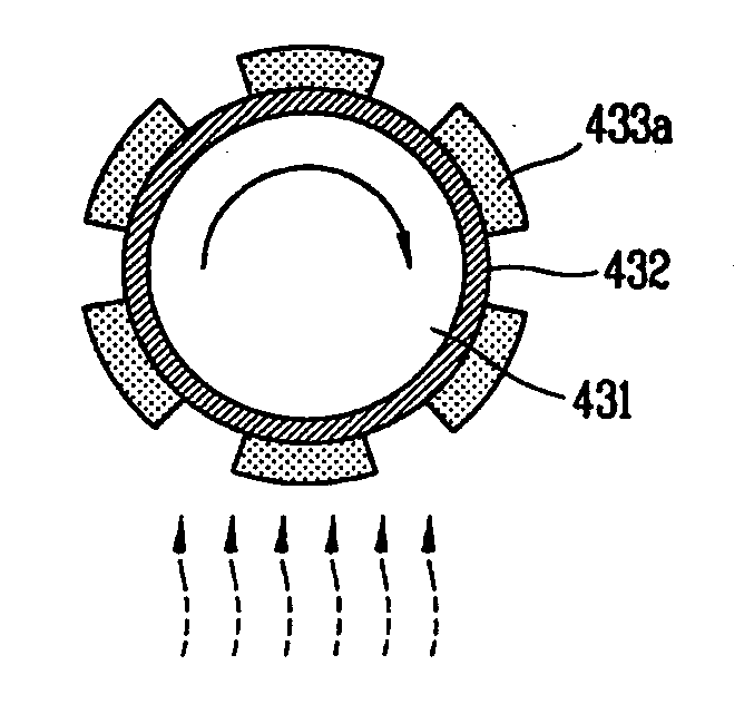
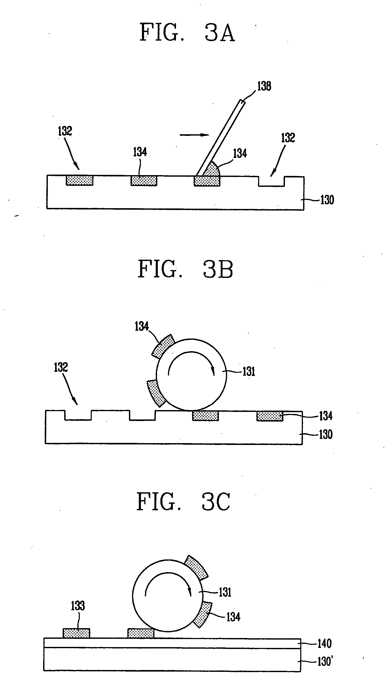
[0026] A gravure offset printing process, in which ink is applied onto a concave plate and surplus ink is etched for printing, may be used in various fields such as a printing for publication, or printing on packages, cellophane, vinyl and polyethylene. In the gravure offset printing, the ink is transferred onto a substrate by using a printing roll. Thus, a pattern can be formed by a single transfer even in a large-sized display device by using a printing roll corresponding to an area of a desired display device. The gravure offset printing may be used to form various kinds of patterns of the display device, for example, not only a TFT but also metal patterns for a capacitor and for a gate line, a data line and a pixel electrode connected to the TFT of an LCD device.

[0027]FIGS. 3A to 3C are schematic views illustrating a method for forming ink patterns on a substrate by using a printing method. As shown in FIG. 3A, in the printing method, grooves 132 are formed at specific location...


PUM

PropertyMeasurementUnit
adhesive forceaaaaaaaaaa
insulatingaaaaaaaaaa
semiconductoraaaaaaaaaa

Abstract

A method for forming a patterns includes applying ink onto an etching object layer; forming ink patterns on the etching object layer as a printing roll having convex patterns thereon rotates on the ink and removes portions of the ink which contact the convex portions of the printing roll, thereby forming ink patterns; and hardening the ink patterns.

Description

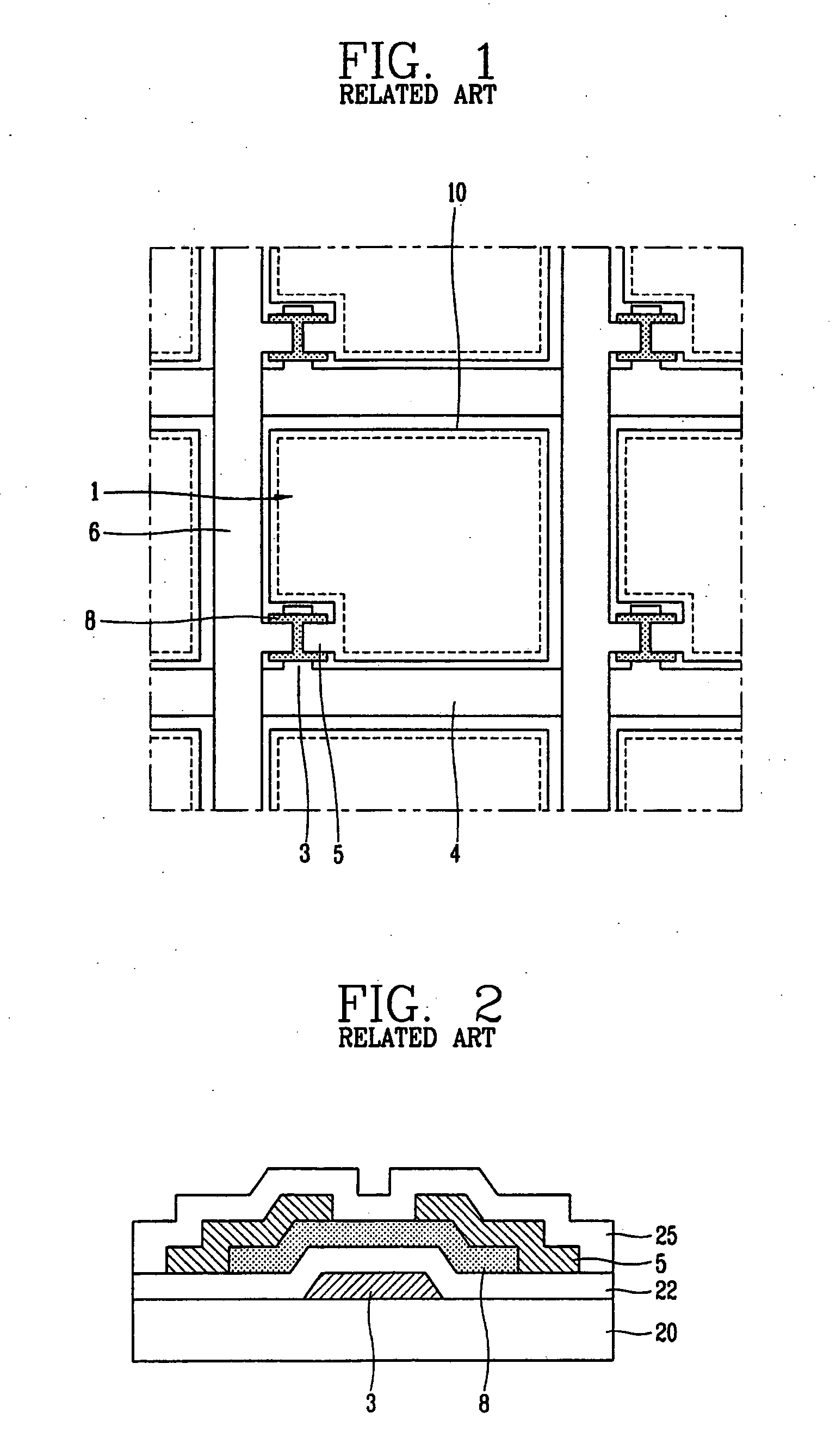
[0001] This application claims the priority benefit of the Korean Patent Application No. 10-2004-0030771 filed on Apr. 30, 2004, which is hereby incorporated by reference. BACKGROUND OF THE INVENTION [0002] 1. Field of the Invention [0003] The present invention relates to a method for forming a pattern using a printing method, and particularly, to a method for forming a pattern using a printing roll having convex patterns. [0004] 2. Description of the Related Art [0005] A display device, especially a flat panel display such as a liquid crystal display (LCD) device, is driven by an active device such as a thin film transistor at each pixel. The driving method is called as an active matrix driving method. According to the active matrix driving method, the active device is arranged at each pixel in a matrix form to drive a corresponding pixel. [0006]FIG. 1 is a view showing an active matrix type LCD device. The LCD device is a TFT LCD device in which a thin film transistor is used as a...

Claims


Application Information

Patent Timeline
Patent Type & Authority Applications(United States)
IPC IPC(8): B41J2/005G02F1/1333H01L21/00
CPCB41J2/0057F24F6/14B05B17/06F24F2221/02Y02B30/70
Inventor KIM, CHUL-HO
Owner LG DISPLAY CO LTD
Learn More