Earphone antenna and portable radio equipment provided with earphone antenna

a portable radio equipment and antenna technology, applied in the field of earphone antennas, can solve the problems of deteriorating antenna performance, affecting reception stability, and inability to obtain sufficient reception sensitivity, so as to reduce the adverse effects of the human body, wide band range, and high gain

Inactive Publication Date: 2005-11-03
SONY CORP
View PDF8 Cites 34 Cited by
  • Summary
  • Abstract
  • Description
  • Claims
  • Application Information

AI Technical Summary

Benefits of technology

[0008] The present invention is contemplated to solve the aforementioned shortcomings associated with the conventional art. It is thus desirable to provide an earphone antenna which is c

Problems solved by technology

In the portable radio equipment which uses a rod antenna or an earphone antenna at the time of use on a human body, there has been a problem that because of a significant deterioration of antenna performance when put on the human body, such as in television broadcasts where signals with a large amount of information, e.g., video signals, are processed, a sufficient reception sensitivity cannot be obtained.
In particular, the earphone antenna which utilizes the signal wire for transmitting audio signals to the earphones as an antenna has had a problem that because the earphones and/or the signal wire make direct contact with the human body,

Method used


Image

  • Earphone antenna and portable radio equipment provided with earphone antenna
  • Earphone antenna and portable radio equipment provided with earphone antenna
  • Earphone antenna and portable radio equipment provided with earphone antenna

Examples


Embodiment Construction

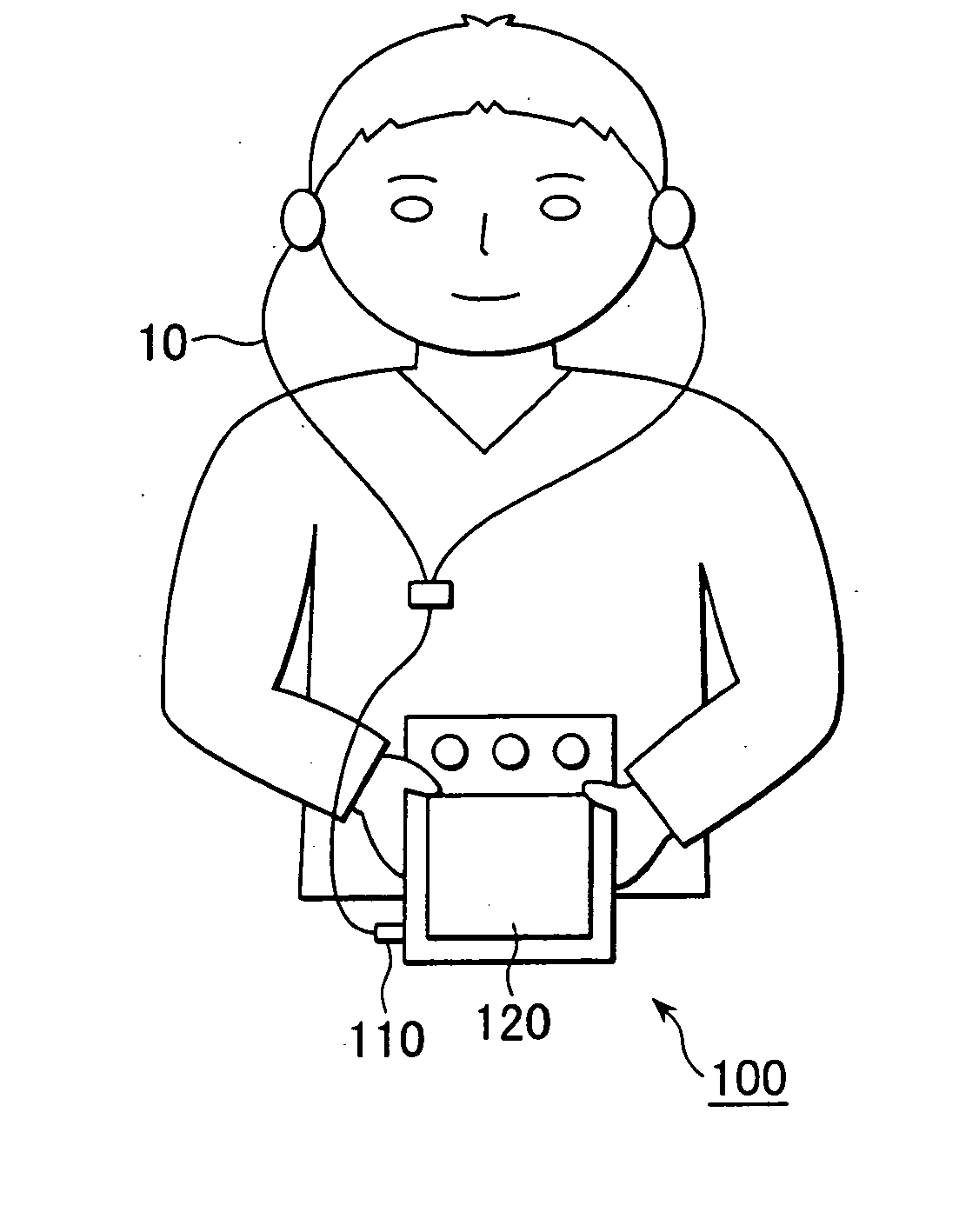
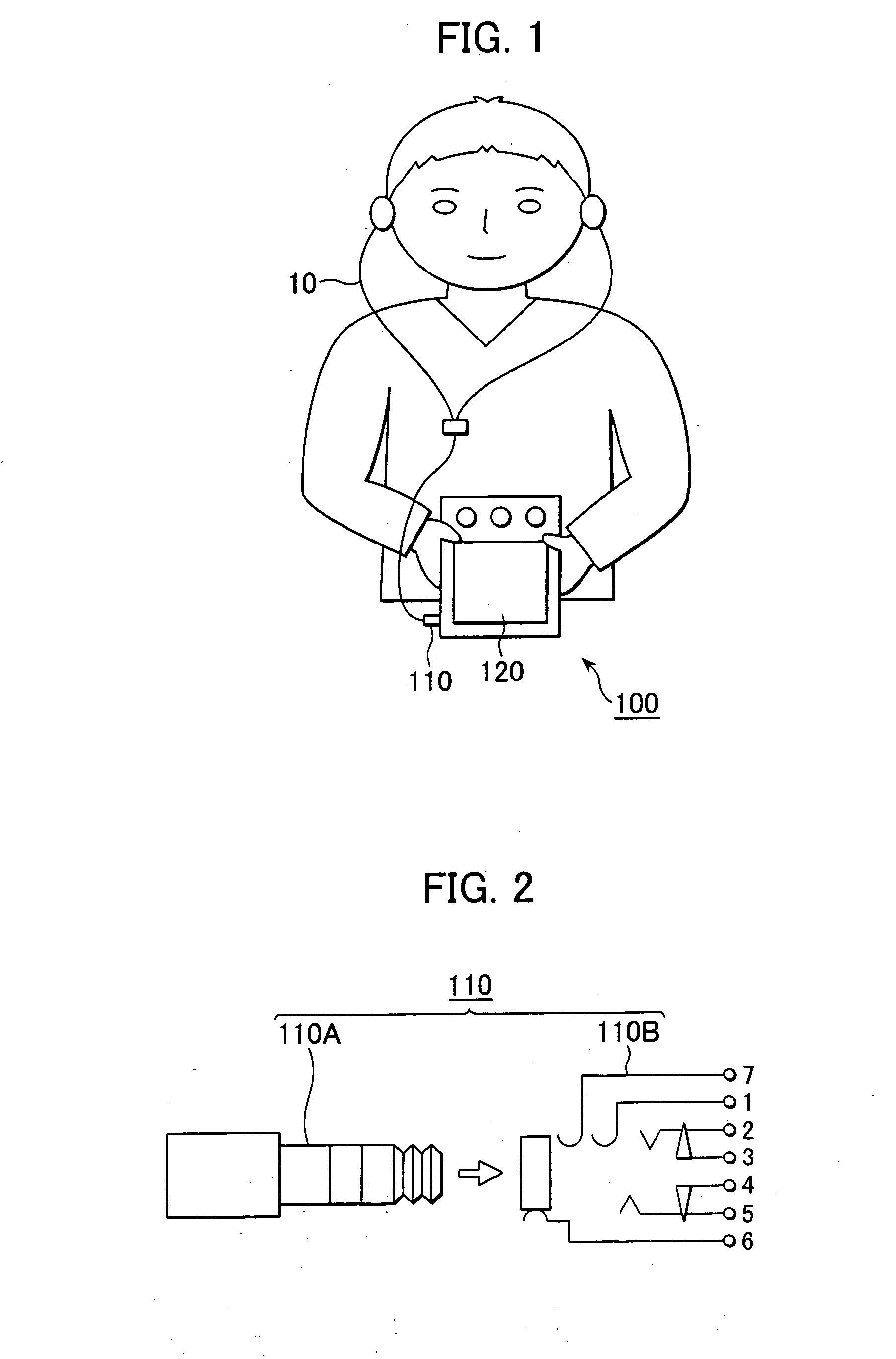
[0026] The present invention is applicable to, for example, an LCD television receiver 100 shown in FIG. 1. In the LCD television receiver 100, an earphone antenna 10 according to an embodiment of the present invention is connected to the main body of the receiver 120 via a pin jack connector 110.

[0027] The pin jack connector 110, as shown in FIG. 2, is composed of a five electrode pin 110A and a jack 110B to which five kinds of lines, including antenna (Ant), headphone detection (detect), audio L channel (L), audio R channel (R), and ground (Gnd) are connected, respectively.

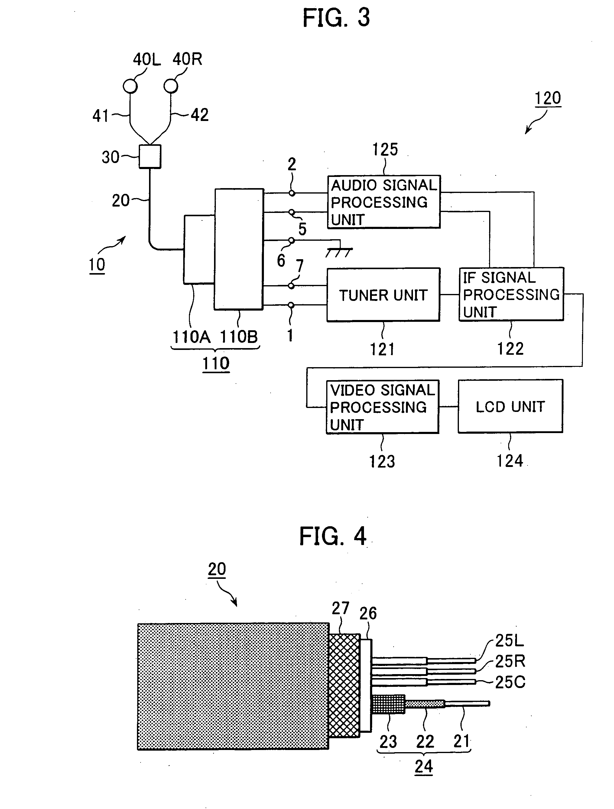
[0028] In the main body of the receiver 120, as shown in FIG. 3, there are provided a tuner unit 121, an IF signal processing unit 122 connected to the tuner unit 121, a video signal processing unit 123 and an audio signal processing unit 125 both connected to the IF signal processing unit 122, a liquid crystal display unit 124 connected to the video signal processing unit 123, and the jack 110B of the pin jac...


PUM


Abstract

An earphone antenna includes an earphone cable having first signal lines; a shielded cable including a coaxial cable, a second signal line for audio signals and a grounding wire, the coaxial cable having a central conductor passing high frequency signals surrounded by an insulator and further surrounded by a first shield wire, the coaxial cable, the second signal line, and the grounding wire collectively being surrounded by a second shield wire; a multipin connector arranged on one end of the shielded cable an adapted to electrically connect the shielded cable to a radio apparatus; and a connection block interconnecting the other end of the shielded cable and the earphone cable. The connection block includes a balun for carrying out impedance and balanced/unbalanced mode transformation, and an audio signal transmission path formed by connecting the second signal line and the grounding wire, respectively, to the pair of first signal lines via a high frequency choke exhibiting low impedance for audio signals and high impedance for high frequency signals. By connecting the central conductor of the coaxial cable and the first shield wire to an unbalanced part of the balun, connecting the pair of first signal lines to one end of a balanced part of the balun via a capacitor exhibiting high impedance for audio signals and low impedance for high frequency signals, and connecting the other end of the balanced part of the balun to the second shield wire, a dipole antenna is formed by the earphone cable and the second shield wire.

Description

CROSS-REFERENCE TO RELATED APPLICATIONS [0001] The present application claims priority from Japanese Patent Application Nos. JP2004-123465 filed on Apr. 19, 2004 and JP2005-030906 filed on Feb. 7, 2005, the disclosures of both of which are hereby incorporated by reference herein. BACKGROUND OF THE INVENTION [0002] The present invention relates to an earphone antenna for portable radio equipment which is put on a human body during use, and portable radio equipment provided with this earphone antenna. [0003] Conventionally, in portable radio equipment, such as a pager, radio receiver, LCD television receiver and the like, which are used by putting on a human body, a rod antenna or an earphone antenna which utilizes a signal wire for transmitting audio signals to earphones is used as an antenna. Such arrangement is disclosed, for example, in JP-A Laid-Open No 2003-163529. [0004] In the portable radio equipment which uses a rod antenna or an earphone antenna at the time of use on a huma...

Claims


Application Information

Patent Timeline
IPC IPC(8): H01Q1/27H01Q1/44H01Q1/46H01Q9/16H04B1/18H04R1/10
CPCH01Q1/273H01Q1/46H01Q5/22H04R1/1033H01Q9/16H02K5/225H02K33/00H04M19/047
Inventor YOSHINO, YOSHITAKA
Owner SONY CORP
Why Eureka
Try Eureka