
Surface plasmon coupled nonequilibrium thermoelectric devices

Inactive Publication Date: 2005-11-10
HON HAI PRECISION IND CO LTD +1
View PDF14 Cites 55 Cited by
  • Summary
  • Abstract
  • Description
  • Claims
  • Application Information

AI Technical Summary

Benefits of technology

[0010] The thickness of the phonon insulating gap is generally from about 1 nanometer to about 100 nanometers, and is typically less than about 10% of the wavelength of the surface-plasmon polaritons. In some embodiments, a second surface-plasmon substrate is coupled to the thermoelectric substrate, and the surface-plasmon substrates are separated by the phonon insulating gap. Generally, each substrate is a semiconductor. Some embodiments include a refrigeration mode. Other embodiments include a power generation mode.
[0011] Such devices and methods are more efficient than those relying on quantum mechanical tunneling of electr

Problems solved by technology

However, phonon heat conduction (i.e., heat conduction due to vibration motion of the atoms in the thermoelectric material) typically reduces the efficiency of such devices, because it tends to transfer additional heat detrimentally from the heat source to the cold reservoir in power generation mode or transfer heat from the hot reservoir to the cooling object in refrigeration mode.
Electron thermionic emission, however, is limited by the work function of available materials.
The total energy transport in these devices is limited by the amount of current that can be transferred via quantum tunneling.
Further, it is difficult to manufacture and maintain the precision gap required for the tunneling effect to operate.
Such devices thus still have some phonon energy transfer and are still limited as above by the amount of current that can be transferred via quantum tunneling.

Method used


Image

  • Surface plasmon coupled nonequilibrium thermoelectric devices
  • Surface plasmon coupled nonequilibrium thermoelectric devices
  • Surface plasmon coupled nonequilibrium thermoelectric devices

Examples


Embodiment Construction

[0038] The foregoing and other objects, features and advantages of the invention will be apparent from the following more particular description of preferred embodiments of the invention, as illustrated in the accompanying drawings in which like reference characters refer to the same parts throughout the different views. The drawings are not necessarily to scale, emphasis instead being placed upon illustrating the principles of the invention.

[0039] The invention generally relates to devices and methods for efficiently transferring thermal energy via coupled surface-plasmon polaritons, while inhibiting unwanted heat conduction due to phonons, and through the high energy flux of the surface plasmon polaritons, creating the nonequilibrium states of electrons and phonons in the thermoelectric element employed.

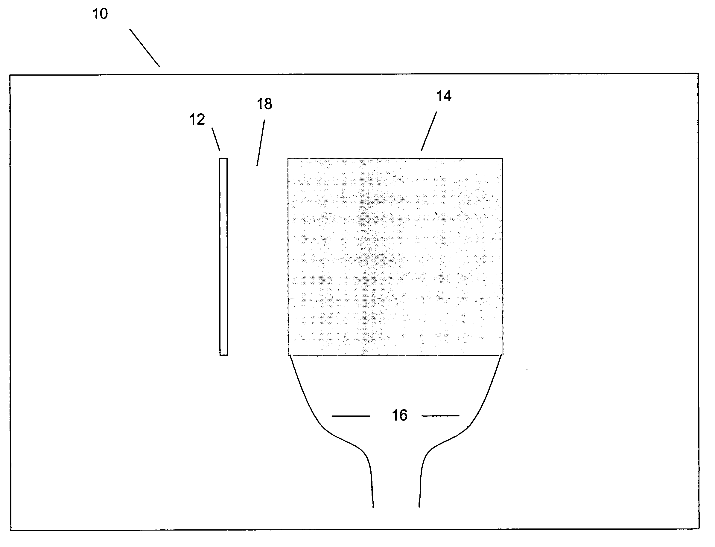
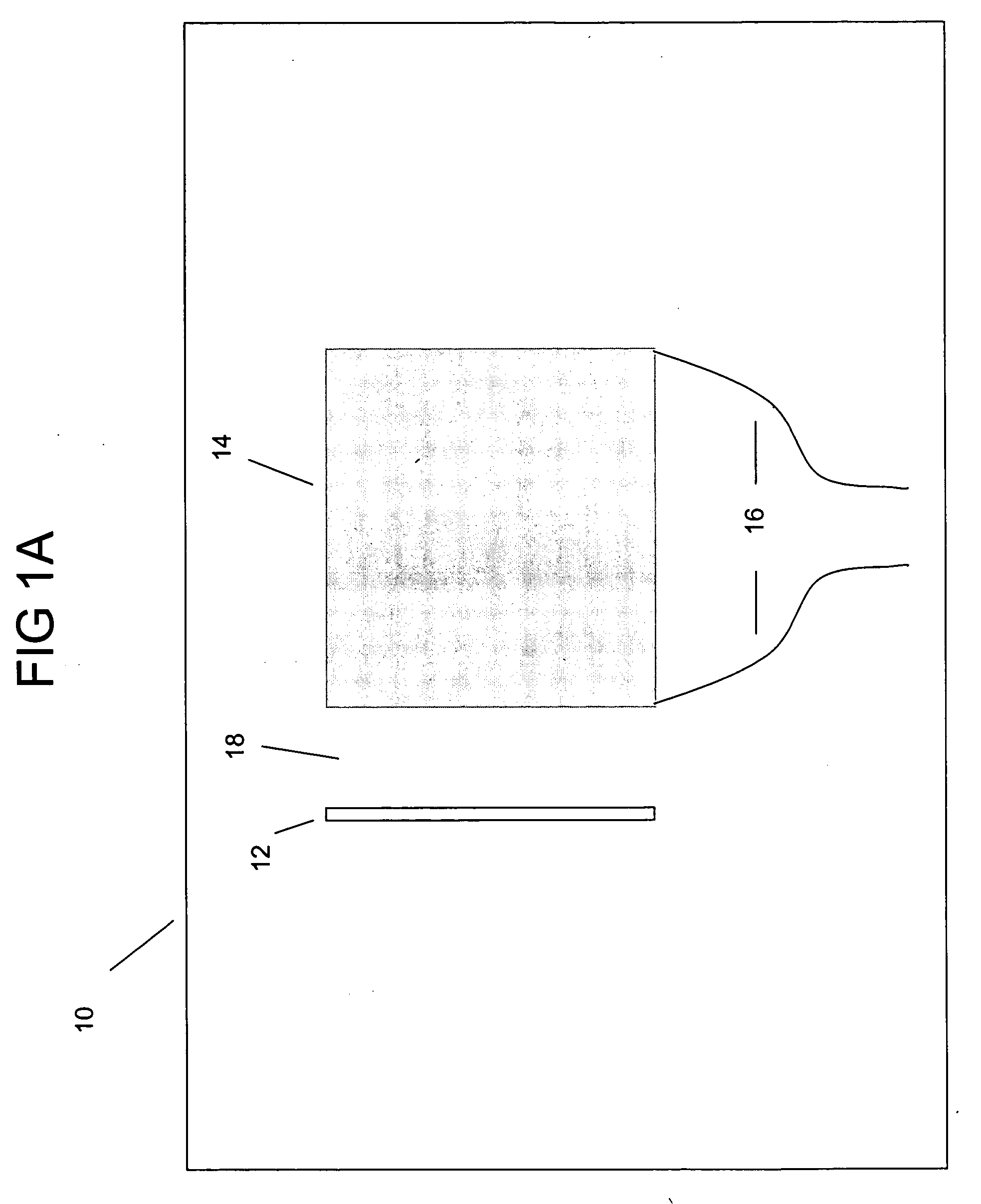
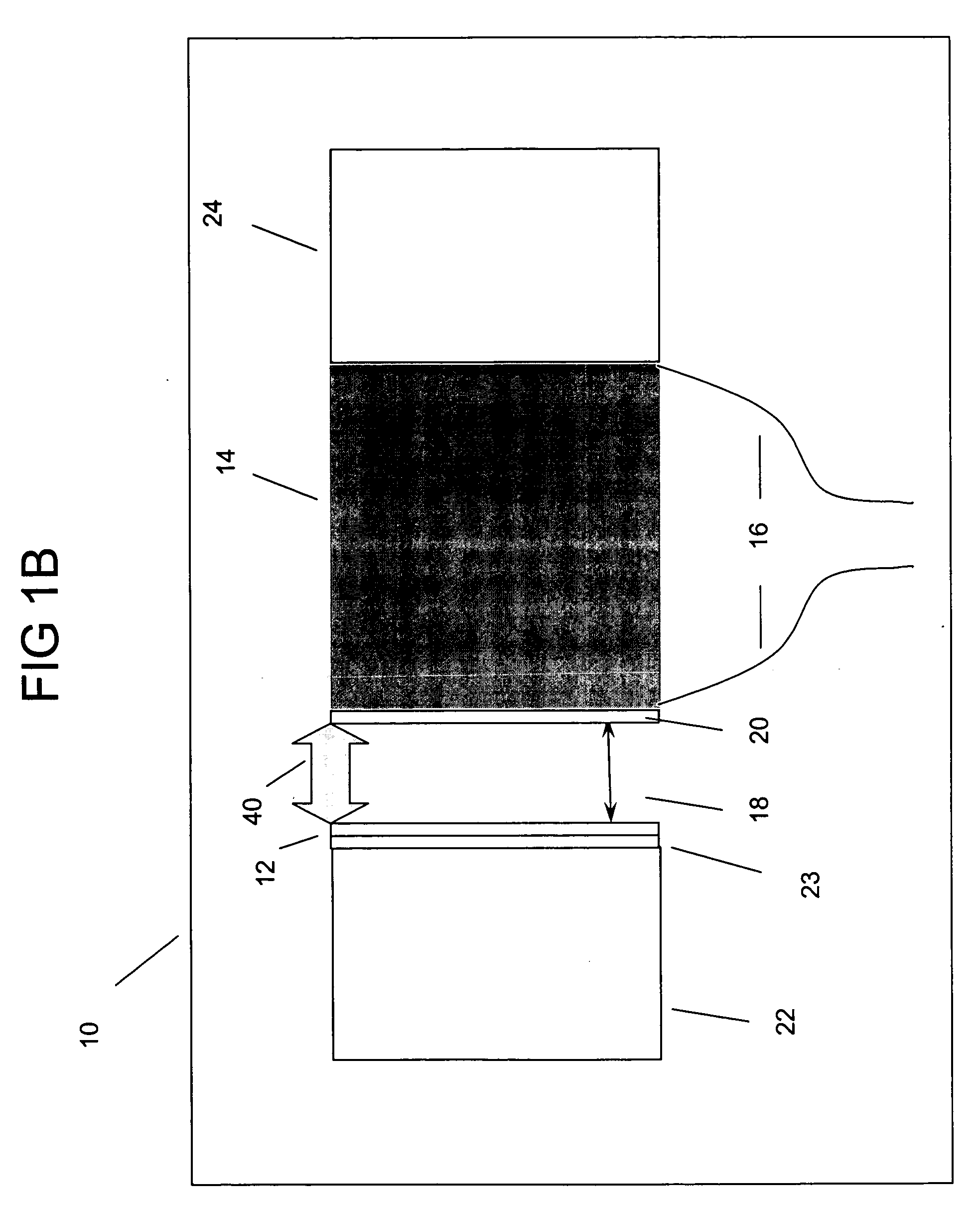
[0040]FIG. 1A depicts surface-plasmon-coupled thermoelectric apparatus 10. First surface-plasmon substrate 12 opposes a first face of thermoelectric substrate 14, defining phonon...


PUM


Abstract

A surface-plasmon-coupled thermoelectric apparatus includes a first surface-plasmon substrate and a thermoelectric substrate electrically coupled to a plurality of electrodes. The substrates are electrically isolated from each other, and a first face of the thermoelectric substrate opposes a first face of the first surface-plasmon substrate to define a phonon insulating gap. A method of transferring thermal energy across the phonon insulating gap includes creating a first surface-plasmon polariton at the first surface-plasmon substrate when the first surface-plasmon substrate is coupled to a first thermal reservoir. Also included is creating a nonequilibrium state between the electron temperature and the phonon temperature at a first face of the thermoelectric substrate, when a second face of the thermoelectric substrate is coupled to a second thermal reservoir. Also included is coupling the first surface plasmon polariton with electrons in the thermoelectric substrate across the phonon insulating gap, thereby transferring thermal energy between the thermal reservoirs through the phonon insulating gap.

Description

RELATED APPLICATION [0001] This application claims the benefit of U.S. Provisional Application No. 60 / 567,987, filed on May 4, 2004 the entire teachings of which are incorporated herein by reference.GOVERNMENT SUPPORT [0002] The invention was supported, in whole or in part, by a grant from the Office of Naval Research / Department of Defense / Multidisciplinary University Research Initiative (ONR / DOD / MURI) on Electromagnetic Metamaterials Through UCLA, Grant No. N00014-01-1-0803. The Government has certain rights in the invention.BACKGROUND OF THE INVENTION [0003] Thermoelectric energy conversion devices employ electrons for energy transfer. Such devices can operate in a refrigeration mode, e.g., by applying a current to transfer heat away from a cooling target, or can operate in a power generation mode, e.g. by using a load circuit to generate power from the temperature difference between two thermal reservoirs. However, phonon heat conduction (i.e., heat conduction due to vibration mo...

Claims


Application Information

Patent Timeline
IPC IPC(8): H01J45/00H01L35/00H01L35/16H01L35/22H01L35/28H01L35/30H01L37/00
CPCH01J45/00H01L35/30H01L35/00H10N10/00H10N10/13
Inventor CHEN, GANGYANG, RONGGUINARAYANASWAMY, ARVIND
Owner HON HAI PRECISION IND CO LTD
Learn More