Connector system

a technology of connecting parts and connecting rods, which is applied in the direction of couplings, pipes, electrical equipment, etc., can solve the problems of difficult to change the coupling part of the hearing aid, difficult to get a constant coupling force, and significant cost and problem for patients, so as to achieve easy removal and replacement of springs, significant cost savings, and high flexibility of the system

Active Publication Date: 2005-11-10
OTICON MEDICAL
View PDF10 Cites 38 Cited by
  • Summary
  • Abstract
  • Description
  • Claims
  • Application Information

AI Technical Summary

Benefits of technology

[0006] In a preferred embodiment the metal spring is mounted in a grove on the outside of the coupling shoes which makes it easy to remove and replace the spring. When the spring has been removed also the coupling shoes can be removed and replaced. This gives a high flexibility of the system and allows also significant cost savings. An important flexibility is that that a spring with suitable stiffness can be chosen for each individual patient which can increase patient safety since it is important that the hearing aid falls off in case of a sudden impact to avoid damaging the fixture in the skull bone. On the other hand it is important to choose as firm coupling as possible for patients wearing a powerful bone anchored hearing aid where it is important that the coupling can transmit significant vibration levels. Another advantage with a steel spring arrangement is that this type of spring has a quite constant spring force during long term use compared with an elastic plastic material acting as a spring. A significant cost saving with this arrangement is that the coupling shoes, which are preferably made of a softer material than the abutment, to minimize the wear on the abutment, can easily be changed when these have been worn out or damaged. The design can include more than two coupling shoes.
[0007] In a preferred embodiment the connector plate has a compression limitation surface hindering the coupling shoes from moving more far to the centre in such a way that the connection can enter and easily be pressed on to the abutment. This is an improvement compared to a more basic design where the coupling shoes goes against each other which might result in hair from the patient being stuck between the coupling shoes since the coupling shoes are more visible than the connector plate.

Problems solved by technology

A drawback with this design is that it is difficult to change the coupling part on the hearing aid when this is worn out.
Significant costs and problems for the patients are caused by the fact that the device needs to be sent in to a special hearing aid repair centre to change the coupling part on the hearing aid.
Another drawback with that design is that it is difficult to get a constant coupling force during the life time of the coupling since there is no reliable metal spring which determines the coupling force and which is more stable during long term use.
Since the invention described in U.S. Pat. No. 5,735,790 does not include any easy removable coupling spring it is also not easy to modify the coupling force for individual fitting of a suitable coupling force for different patients.
An arrangement intended to hinder such damage is likely to increase the collection of dirt in the coupling.
This design also results in a very varying coupling force during the life time of the device.
A design like the one described in SE0102207 has several drawbacks since it includes magnetic components which are not compatible with MRI equipment used at hospitals and a small magnetic circuit can not generate the force needed to keep the hearing aid properly in place.

Method used


Image

  • Connector system
  • Connector system
  • Connector system

Examples


Embodiment Construction

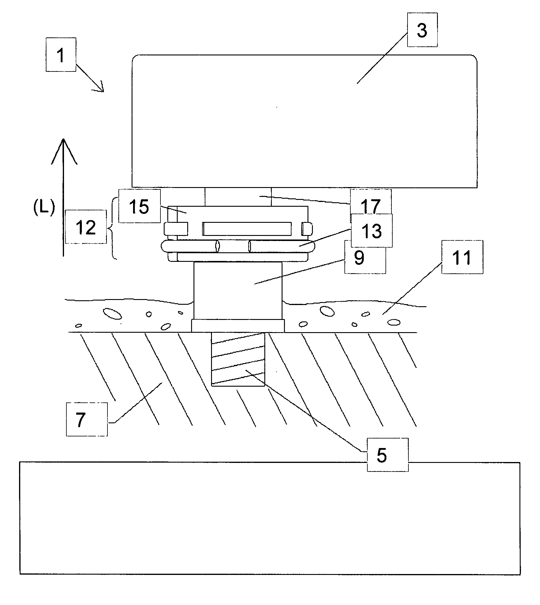
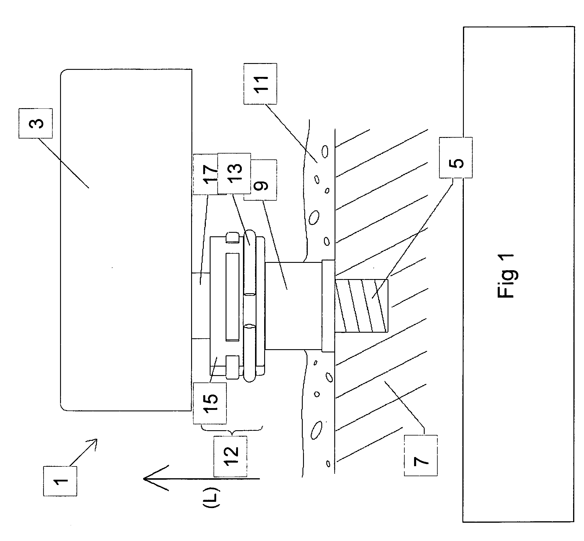
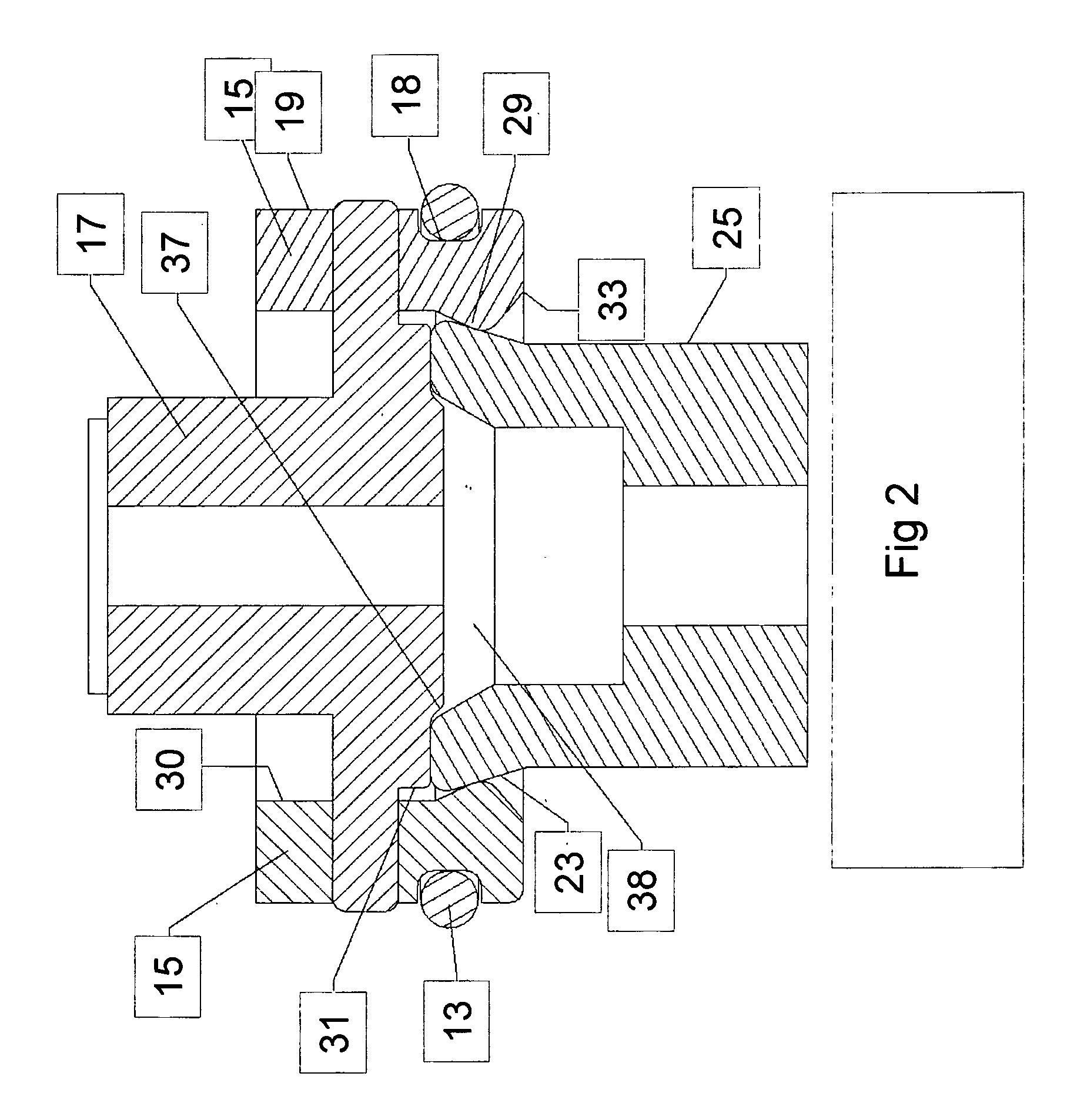
[0017] In FIG. 1, a preferred embodiment of a connector system 1 for interconnecting a hearing aid 3 with a fixture 5 anchored in the skull bone 7 is shown. A connector 8 is on one side in operative engagement with an abutment 9 which is mounted on the fixture 5 and which goes through the skin 11. The other opposite side of the connector 8 is in operative engagement with a connector plate 17 that is connected to the hearing aid 3. The connector 8 includes a circular metal spring 13 and two coupling shoes 15 mounted on the connector plate 17. The spring 13 is removably attached to a groove 18 defined on an outside surface 19 of the shoes 15. In FIG. 2 the connector plate 17 has a circular connector contact surface 20 that is in contact with a contact surface 21 of the abutment 9. An abutment coupling area 23 on an outer mantle surface 25 of the abutment 9 is conical with a conical angle 27 relative to a centre axis of the abutment and has an increasing diameter in a lateral direction...


PUM


Abstract

A connector system for interconnecting a hearing aid (3) with a fixture (5) anchored in a bone segment (7). An abutment (9) has a contact surface (21) with is a substantially circular surface. A connector plate (17) with a substantially circular connector contact surface (20) is in contact with the abutment contact surface (21) when the hearing aid (3) is connected to the abutment (9). The abutment (9) has a wide abutment coupling area and a narrow portion. The abutment coupling area is enclosable by coupling shoes (15). The coupling shoes (15) exert a pressure against the abutment coupling area disposed on a mantle surface (25) of the abutment. The coupling shoes are movable in a radial direction relative to the connector plate (17). The coupling area has an increasing diameter in a lateral direction (L). A coupling area (29) of the coupling shoes has an increasing diameter in the lateral direction (L) to exert a pressure on the abutment (9) against a connector contact surface when the coupling shoes (15) are pressed in the radial direction against the abutment (9).

Description

TECHNICAL FIELD [0001] The present invention relates to a connector system for interconnecting a bone anchored implant with a bone conduction hearing aid. BACKGROUND OF THE INVENTION [0002] Bone anchored hearing aids are essential for the rehabilitation of patients suffering from some specific type of hearing losses for which traditional hearing aids are insufficient. This type of device consists of an external hearing aid with a vibrating transducer which is connected via a connector to a skin penetrating abutment mounted on a fixture anchored in the skull bone. The abutment can be mounted on the fixture with a small screw going through the centre of the abutment and into a threaded hole in the fixture. It is important that the coupling between the hearing aid and the abutment is sufficiently firm to avoid poor transmission of the vibrations but it is also important that the coupling is not too firm since it is also important that the hearing aid falls off in case of a sudden impac...

Claims


Application Information

Patent Timeline
Patent Type & Authority Applications(United States)
IPC IPC(8): F16L23/04F16L35/00
CPCF16L23/04H04R2460/13H04R2225/67H04R25/606
Inventor WESTERKULL, PATRIK
Owner OTICON MEDICAL
Why Eureka
Try Eureka