Composite protection for revealing damage to a core in a vehicle such as an aircraft

a technology for aircraft and cores, applied in aircraft indicators, air transport, vibration dampers, etc., can solve the problems of general sensitiveness of structural assemblies, loss of cohesion between the various, and specific mode of degradation

Inactive Publication Date: 2005-11-10
EUROCOPTER
View PDF6 Cites 14 Cited by
  • Summary
  • Abstract
  • Description
  • Claims
  • Application Information

AI Technical Summary

Benefits of technology

[0072] From the above, it will be understood that an object of the invention is to provide protection that reveals damage that has been generated in a composite structural assembly (referred to as a “core”) by at least one type of environmental aggression, including impact.

Problems solved by technology

Nevertheless, whatever their type, when they have at least two plies of impregnated textile reinforcement, structural composite assemblies present mechanical behavior that is strongly anisotropic and they thus present a specific mode of degradation in the face of external attack.
Because of their stratified composition, and because of the weak mechanical properties of the plies in directions that are transverse to the direction of the reinforcement, such composite structural assemblies are generally sensitive to shock or impact concentrated at a point.
Shocks or impacts cause delamination and loss of cohesion between the various plies of a composite structural assembly.
The delamination and loss of cohesion can lead to complete failure in the mechanical behavior of a composite structural assembly.
Mostly, when the delamination occurs within the composite assembly, it is not always identifiable by ordinary inspection techniques, in particular visual inspection.
Thus, unlike metal structures, the damage caused by an impact is not visually detectable on a composite structure.
Unfortunately, in numerous examples of composite structure assemblies, integrity of the assembly is essential for the safety of the intended vehicle and its passengers.
It will be understood firstly that such inspection techniques are not completely reliable.
Secondly, they are difficult and often expensive to implement.
In particular it is often necessary to take the vehicle temporarily out of service for inspection purposes, which is penalizing in operating terms, particularly in the field of aviation.
To sum up, composite structural assemblies are subjected in practice to damage because of the impacts and shocks they suffer, which can lead to situations that can become catastrophic insofar as the damage can be hidden and go unrepaired.
Such overdimensioning is particularly important when using unidirectional textile reinforcement, since such reinforcement is less tolerant to damage than is continuous woven reinforcement.
In addition, composite structural assemblies that are overdimensioned in this way lose some of the advantage associated with the light weight of composite materials, e.g. when compared with metals.
Nevertheless, the highly hygroscopic behavior of such high-strength fibers leads to problems due to moisture being absorbed and degrading the interface between the fibers and the matrix.
Furthermore, such fibers are difficult to work and to cut, so they are particularly expensive and difficult to implement industrially.
Unfortunately, matrices including thermoplastic plasticizers are expensive and they affect the mechanical performance of composite structural assemblies in ways unrelated to impact resistance, for example stiffness at high temperature.
In addition, those solutions do not solve the crucial problem of revealing damage.
In addition to impact, the intrinsic mechanical characteristic of composite structural assemblies can also be degraded by other kinds of attack from the environment.
To counter such environmental attack, the problem of providing protection and of revealing damage does not have a prior art solution, any more than does the problem of impact damage.

Method used


Image

  • Composite protection for revealing damage to a core in a vehicle such as an aircraft
  • Composite protection for revealing damage to a core in a vehicle such as an aircraft
  • Composite protection for revealing damage to a core in a vehicle such as an aircraft

Examples


Embodiment Construction

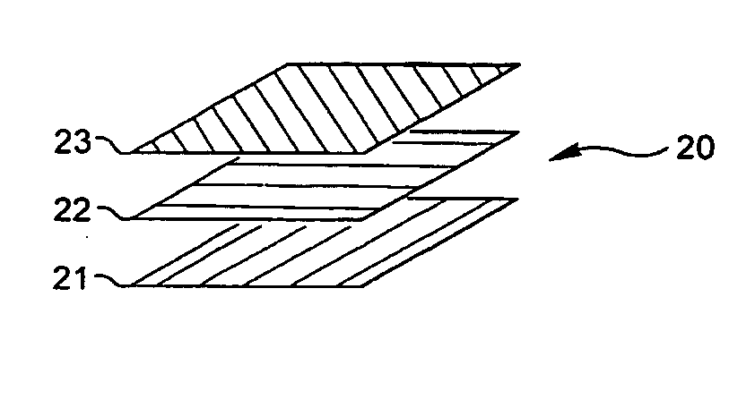
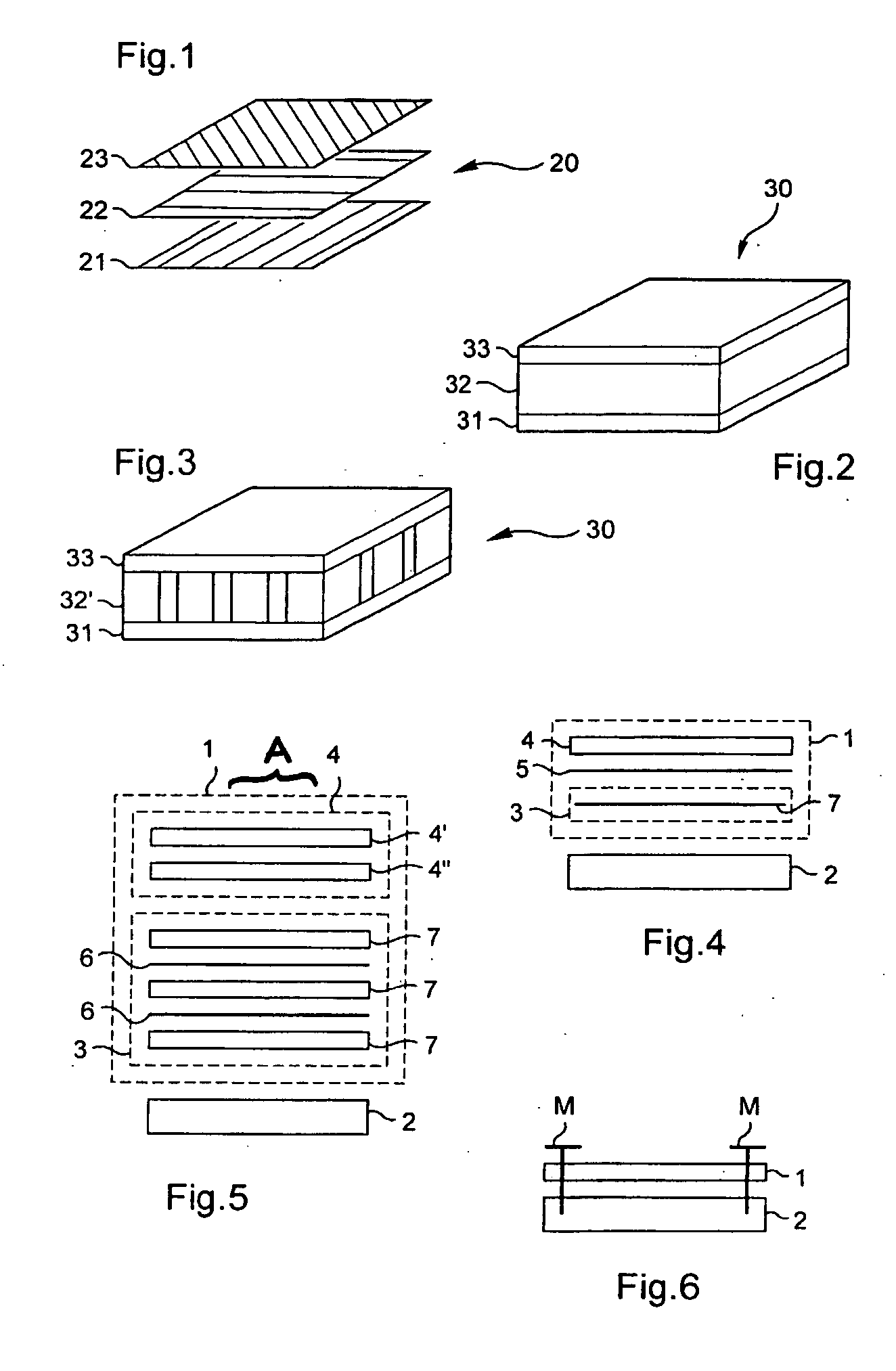
[0115]FIG. 1 shows a prior art composite structural assembly 20 of monolithic type.

[0116] The assembly 20 is constituted by stacking individual plies comprising textile reinforcement impregnated in an organic matrix. The plies 21, 22, and 23 have respective orientations of 0°, 90°, and 45°.

[0117]FIG. 2 shows a prior art composite structural assembly 30 of the sandwich type.

[0118] The assembly 30 is provided with a foam core 32 disposed between two layers 31 and 33 of textile reinforcement impregnated in an organic matrix.

[0119]FIG. 3 shows a prior art composite structural assembly 30 of the sandwich type, but in this case it has a honeycomb core 32′, i.e. a core having hollow cells.

[0120] The honeycomb core 32′ is disposed between two layers 31, 33 of textile reinforcement impregnated in an organic matrix.

[0121]FIG. 4 is a section through a structural assembly having a main core 2.

[0122] It is appropriate to recall at this point that such a main core 2 is subjected to static ...


PUM

PropertyMeasurementUnit
temperatureaaaaaaaaaa
elastomericaaaaaaaaaa
energyaaaaaaaaaa

Abstract

The composite structure for protecting a main core comprises a laminated surface covering having a rigid protective layer and an elastomeric member. A damage tell-tale is inserted between the rigid protective layer and the elastomeric member. The composite structure thus serves both to protect the core and to reveal damage suffered by the core. The structure is applicable, for example, to protecting a structural element of a vehicle such as a helicopter.

Description

FIELD OF THE INVENTION [0001] The invention relates to protecting a structural assembly of a transport vehicle, such as an aircraft. Such a “structural assembly” is referred to below by the term “core”. [0002] In the meaning of the invention, a “structural assembly” or “core” is a mechanical assembly such as a single part or a functional group of parts that is to constitute a portion of the vehicle and that, once integrated in the vehicle, contributes to its normal operation. [0003] The invention serves to protect such a core against damage. [0004] In addition, still in the meaning of the invention, the core to be protected is said to be “structural” since it is stressed during normal operation of the vehicle by loading that is static and / or dynamic. [0005] The core may be subjected, in operation, to damage due to attack (impact, erosion, nicking or grooving, lightning, flame, heat, etc.) from the environment surrounding the vehicle. [0006] Nevertheless, the core is such that intrin...

Claims


Application Information

Patent Timeline
Patent Type & Authority Applications(United States)
IPC IPC(8): B32B25/04B32B33/00B60N2/42B64C1/00B64D45/00F16F1/373F16F7/00F16F7/12
CPCB64C1/062B64C2001/0072F16F1/3737B32B25/04F16F7/12Y02T50/433F16F7/00Y02T50/40B32B15/06B32B2605/18B32B2307/56
Inventor AZEAU, JEAN
Owner EUROCOPTER
Why Eureka
Try Eureka