Constant-voltage circuit

a constant-voltage circuit and circuit technology, applied in the direction of amplifiers, amplifiers with semiconductor devices/discharge tubes, instruments, etc., can solve the problems of affecting the signal transfer rate, the frequency at which the null point is reached, and the inability to obtain suitable phase compensation, etc., to achieve stable signal transfer

Active Publication Date: 2005-11-10
NISSHINBO MICRO DEVICES INC
View PDF8 Cites 31 Cited by
  • Summary
  • Abstract
  • Description
  • Claims
  • Application Information

AI Technical Summary

Benefits of technology

[0043] As described above, according to the constant-voltage circuit of the present invention, the internal output voltage of the constant-voltage circuit is raised by a current proportional to the output current to a part of output voltage detection resistances. In this manner, the voltage drop by the resistance prepared for phase compensation is compensated for, and a capacitor having a small internal resistance like a ceramic capacitor can be used for phase compensation. Further, the low side voltage of the load is made equal to the grounding voltage, providing stable signal transfer to and from the load.

Problems solved by technology

Accordingly, when the ceramic capacitor is used for phase compensation, the frequency at which a null point is obtained moves to a very high frequency, and suitable phase compensation cannot be obtained.
However, it is disadvantageous for space and cost reasons.

Method used


Image

  • Constant-voltage circuit
  • Constant-voltage circuit
  • Constant-voltage circuit

Examples


first embodiment

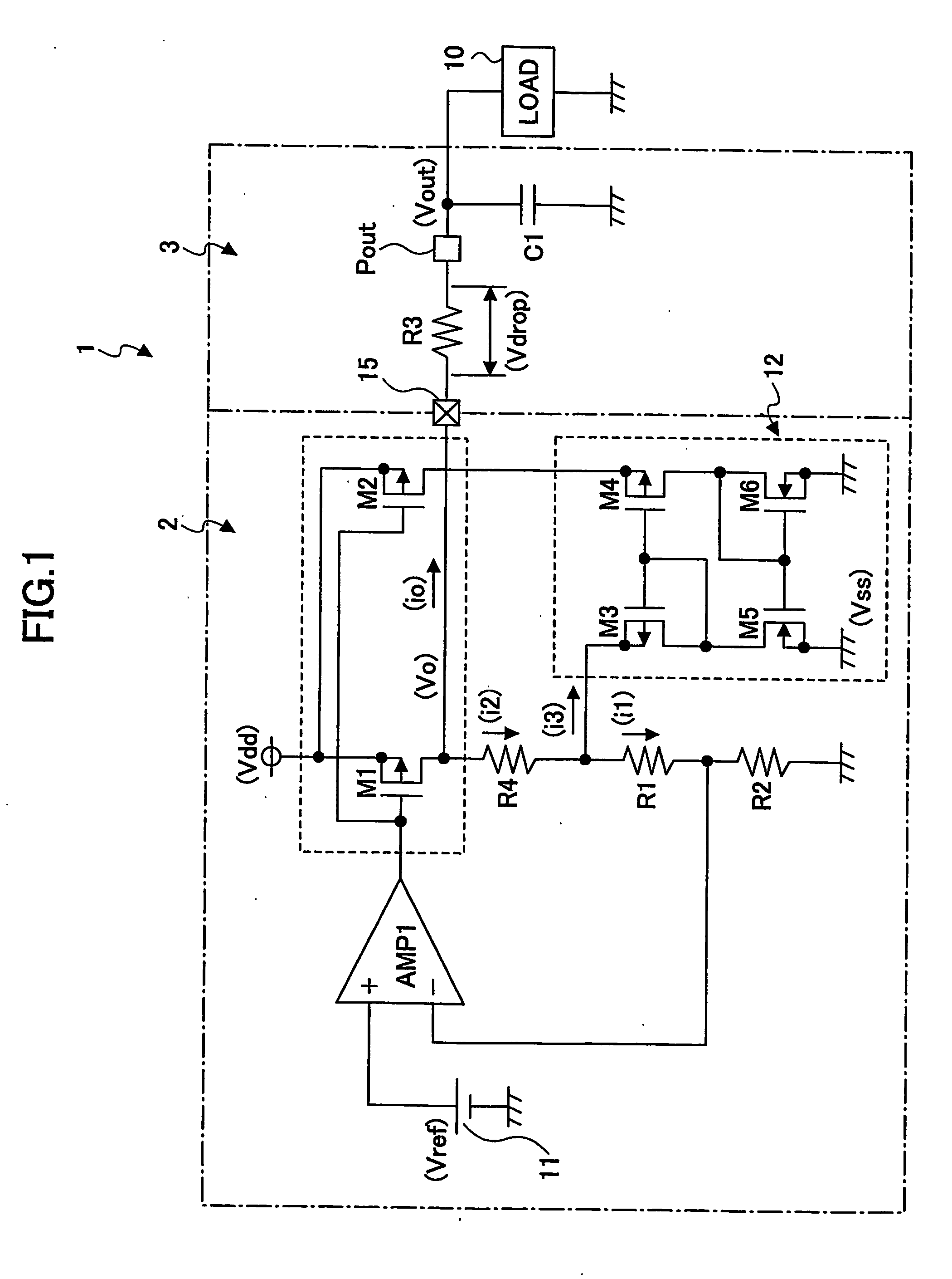
[0044]FIG. 1 is an example circuit diagram of a constant-voltage circuit according to the present invention.

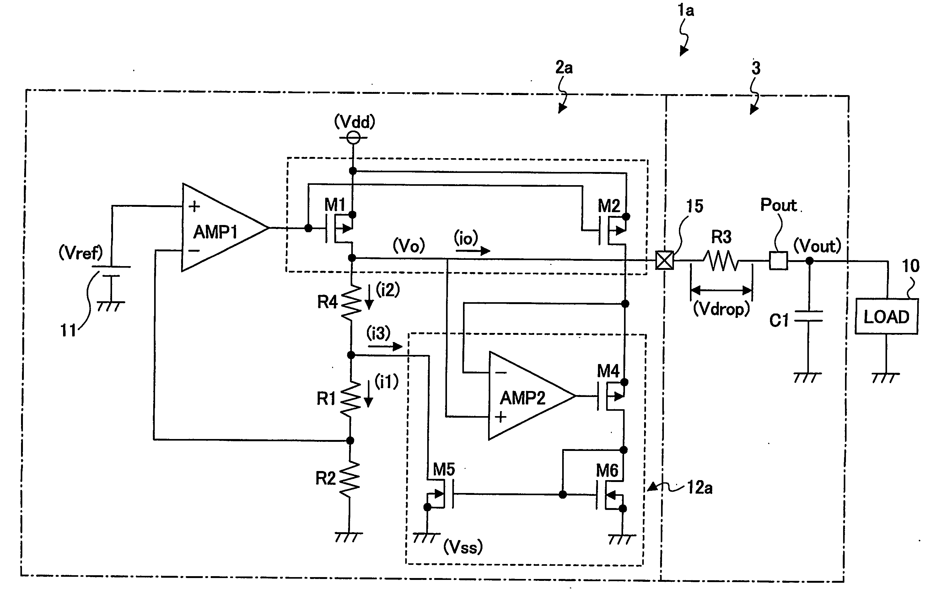
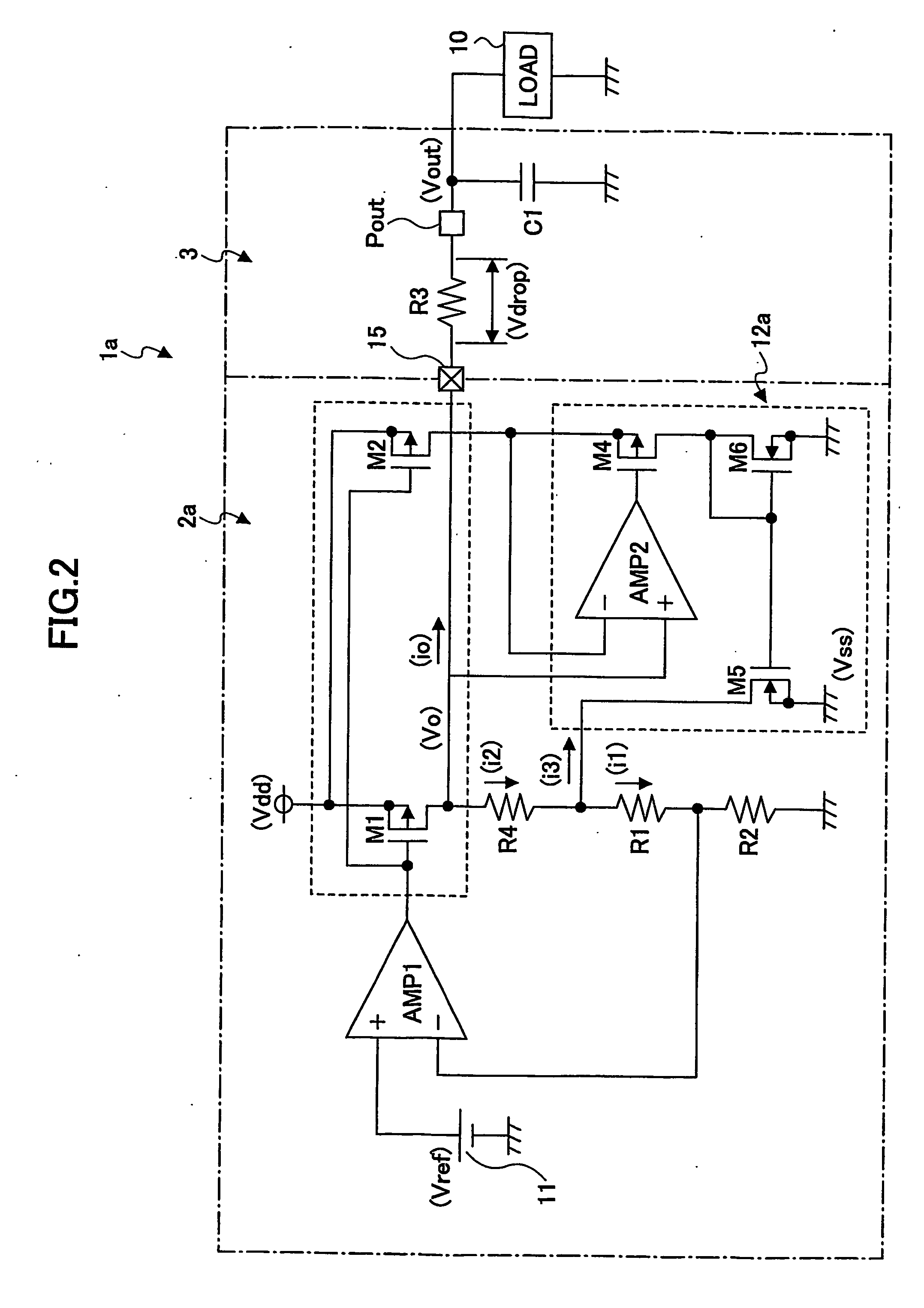
[0045]FIG. 2 is another example circuit diagram of the constant-voltage circuit according to the first embodiment of the present invention.

[0046]FIG. 3 is an example circuit diagram of a conventional constant-voltage circuit.

[0047]FIG. 4 shows an example of an equivalent circuit of a tantalum capacitor.

[0048]FIG. 5 shows an example of an equivalent circuit of a ceramic capacitor.

[0049]FIG. 6 is an example circuit diagram of a conventional constant-voltage circuit.

[0050]FIG. 7 is an example circuit diagram of another conventional constant-voltage circuit.

BEST MODE FOR CARRYING OUT THE INVENTION

[0051] In the following, embodiments of the present invention are described with reference to the accompanying drawings.

[0052] [First Embodiment]

[0053]FIG. 1 shows an example of a circuit of a constant-voltage circuit 1 according to the first embodiment of the present invention.

[0...


PUM


Abstract

A disclosed constant-voltage circuit uses a capacitor having a low ESR (equivalent serial resistance), such as a ceramic capacitor, for phase compensation, wherein a voltage drop of an output voltage due to a resistance provided for optimizing the phase compensation is compensated for by providing a current proportional to an output current to an output voltage detecting resistance through a current mirror circuit, thereby the voltage drop of the output voltage is compensated for.

Description

TECHNICAL FIELD [0001] The present invention generally relates to a constant-voltage circuit, and especially relates to a constant-voltage circuit that is capable of performing phase compensation using a low ESR (Equivalent Serial Resistance) capacitor by providing a circuit for compensating for a voltage drop of an output voltage caused by an output resistance. BACKGROUND ART [0002] Conventionally, a power unit that is capable of compensating for a voltage drop at a load due to wiring without using two remote sensing lines for low cost has been available, for example, as disclosed by Patent Reference 1. [0003] Further, in order to perform phase compensation for a constant-voltage circuit, conventionally, a capacitor is often provided at the output terminal of the constant-voltage circuit in parallel to the load as shown in FIG. 3. An internal impedance of ESR and a capacitance of a capacitor C101 provide the phase compensation, and improve the frequency characteristics of the const...

Claims


Application Information

Patent Timeline
Patent Type & Authority Applications(United States)
IPC IPC(8): G05F1/56G05F1/575G05F3/24G05F3/26H03F3/347
CPCG05F1/575G05F1/56
Inventor ITOH, KOHZOH
Owner NISSHINBO MICRO DEVICES INC
Why Eureka
Try Eureka