Device for holding a beam splitter element

a splitter element and beam technology, applied in the field of beam splitter element devices, can solve the problems of displacement, worsening the imaging behavior of the catadioptric projection objective of the projection exposure machine, and affecting the accuracy of the beam path, so as to achieve precise and stable beam path

Inactive Publication Date: 2005-11-10
CARL ZEISS SMT GMBH
View PDF8 Cites 4 Cited by
  • Summary
  • Abstract
  • Description
  • Claims
  • Application Information

AI Technical Summary

Benefits of technology

[0007] It is therefore the object of the present invention to provide a device for holding a beam splitter element having an optically active beam splitter layer of the type mentioned at the beginning and which disposes of the disadvantages of the prior art and permits a precise and stable beam path through the beam splitter element, in particular during operation.

Problems solved by technology

In the case of mounts, which hold such a beam splitter cube in the region of one or more of its side faces, undesired movements such as displacements or rotations of the beam splitter layer in the interior of the beam splitter cube, can occur.
This movement, which stems, from the length expansions of the material of the beam splitter cube and, on the other hand, from deformations of the beam splitter layer owing to thermally induced stresses, worsens the imaging behavior of the catadioptric projection objective of the projection exposure machine.
In addition, the beam splitter cube and the beam splitter layer can also themselves be deformed such that not only is the beam wrongly deflected, but aberrations occur in the imaging of the projection objective.
Such undesired changes of the beam splitter layer can also occur, of course, in the event of global warming in the objective.

Method used


Image

  • Device for holding a beam splitter element
  • Device for holding a beam splitter element
  • Device for holding a beam splitter element

Examples


Embodiment Construction

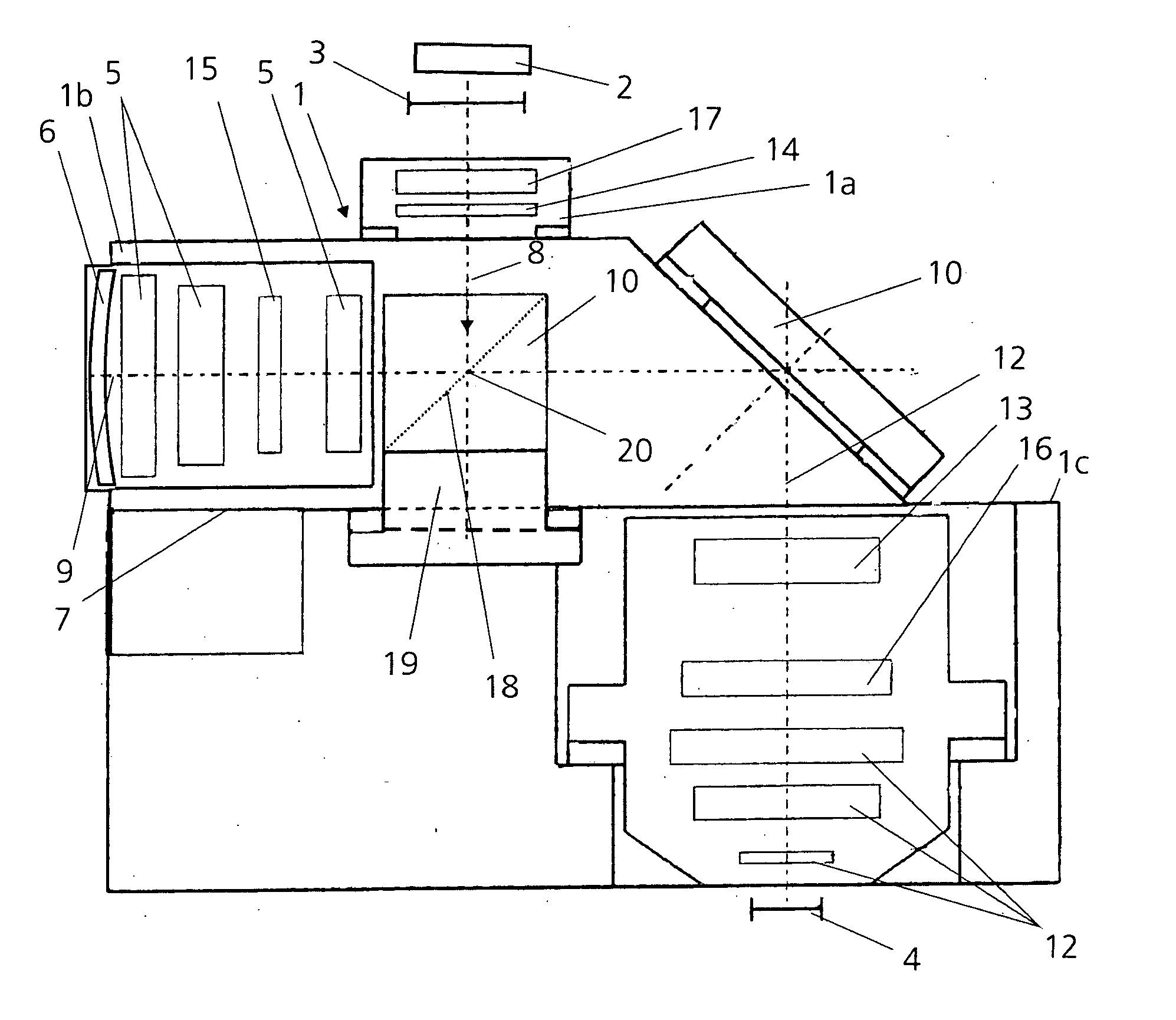
[0037]FIG. 1 is a schematic representation of a projection exposure machine having a projection objective 1 for microlithography, for the purpose of producing semiconductor components.

[0038] It has an illumination system 2 with a laser (not illustrated) as light source. Located in the object plane of the projection exposure machine is a reticle 3 whose structure is to be imaged at an appropriately reduced scale onto a wafer 4 that is arranged below the projection objective 1 and is located in the image plane.

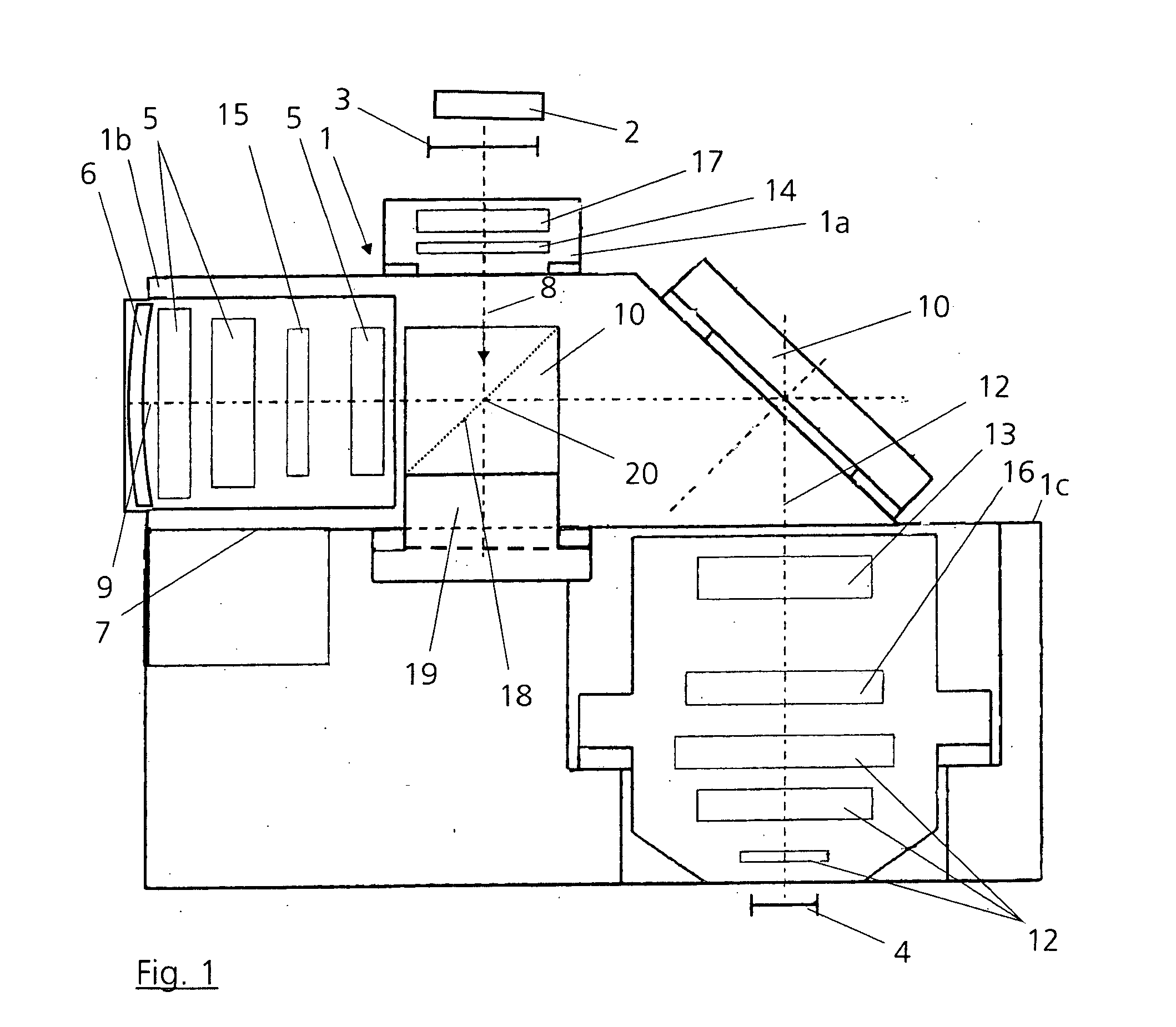
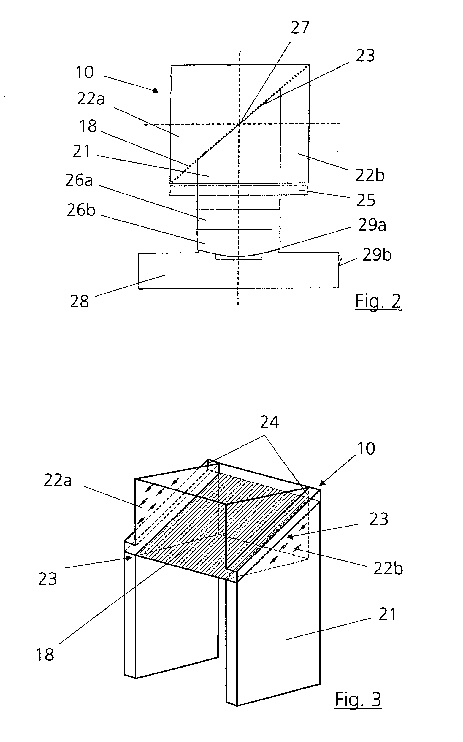
[0039] The projection objective 1 is provided with a first vertical objective part 1a and a second objective part 1b, which is at least approximately horizontal or inclined at up to 30° to the horizontal. Located in the objective part 1b are a number of lenses 5 and a concave mirror 6, which are arranged in an objective housing 7 of the objective part 1b. A beam splitter cube 10 is provided for deflecting the projection beam (see arrow) from the vertical objective part 1a with...


PUM

PropertyMeasurementUnit
temperaturesaaaaaaaaaa
thermal stressesaaaaaaaaaa
temperatureaaaaaaaaaa

Abstract

The invention relates to a device for holding a beam splitter element having an optically active beam splitter layer in an optical imaging device, the beam splitter element being connected to at least one support element that is fastened in the housing of the imaging device. The connection between the beam splitter element and said at least one support element is designed in such a way that the position of the beam splitter layer of the beam splitter element remains nearly constant relative to the housing independently of temperatures and of thermal stresses acting upon the beam splitter element.

Description

BACKGROUND OF THE INVENTION [0001] 1. Field of the Invention [0002] The invention relates to a device for holding a beam splitter element having an optically active beam splitter layer in an optical imaging device, the beam splitter element being connected to at least one support element that is fastened in the housing of the imaging device. [0003] 2. Description of the Related Art [0004] In projection exposure machines for microlithography having catadioptric projection objectives that have a polarizing beam splitter cube, the beam splitter cube deflects the light beam coming from the reticle into a cantilever arm with a concave mirror, while the light beam returning from the cantilever arm is let directly through the beam splitter cube. In this case, temperature changes during the ongoing operation result, in particular, from the absorption of light in the beam splitter layer of the beam splitter cube, but also from that in other layers as well as in the entire volume of the beam ...

Claims


Application Information

Patent Timeline
Patent Type & Authority Applications(United States)
IPC IPC(8): G02B7/00G02B7/18G03F7/20
CPCG02B7/008G03F7/70891G03F7/70825G02B7/1805
Inventor WEBER, ULRICHKOHL, ALEXANDERHOLDERER, HUBERTSCHOEPPACH, ARMINGABER, ERWINKAISER, WINFRIEDGARREIS, REINERGRUNER, TORALFREED, CHRISPARIZA, DRAGOSMEEHAN, MIKE
Owner CARL ZEISS SMT GMBH
Why Eureka
Try Eureka