Electromagnetic valve actuation with series connected electromagnet coils

a technology of electromagnet coils and electric valves, applied in the field of system and method of valve actuation, can solve problems such as wasted energy, and achieve the effect of reducing or eliminating force and simplifying valve actuation

Inactive Publication Date: 2005-11-10
FORD GLOBAL TECH LLC
View PDF14 Cites 7 Cited by
  • Summary
  • Abstract
  • Description
  • Claims
  • Application Information

AI Technical Summary

Benefits of technology

[0009] The present invention provides for simplified valve actuation using a modified “H” bridge arrangement by recognizing that the upper and lower electromagnet coil forces are essentially independent. As such the upper and lower electromagnet coils are arranged in series to provide respective attractive forces such that current switching or reversal through the coils is not necessary. Start-up control may be provided by appropriate selection of coil strengths, one or more permanent magnets, or using a switching device to reduce or eliminate the force generated by one of the electromagnets, for example.
[0010] Embodiments of the present invention include a system and method for actuating a valve having an armature coupled to a valve stem and movable between first and second electromagnets having series connected coils during an opening or closing event to open and close the valve, such as an intake or exhaust valve of an internal combustion engine. The opening or closing events include a launch from a first (holding) electromagnet, travel or flight of the armature across a gap between the first and second electromagnets, a catch by the second (catching) electromagnet, and a hold by the second electromagnet. The current supplied to the electromagnets is reduced so that the force of the holding electromagnet (and permanent magnet if present) is less than the opposing force of its associated spring to launch the armature. The system and method use conservation of magnetic flux to transfer energy stored in the first electromagnet to the second electromagnet, directly in one embodiment, or via an energy storage device controlled through a switching element in another embodiment. In one embodiment, the system and method may reverse the polarity of the voltage applied to the series connected coils to more quickly transfer the energy to the catching coil to achieve a desired system response time and reduce losses.
[0013] The present invention provides a number of advantages. For example, the present invention reduces the power electronics required by arranging the coils in series so that both coils are driven by common power electronics. Relative to a conventional “H” bridge arrangement for each coil, the present invention reduces the drive electronics by half. A series coil arrangement according to the present invention also reduces the number of power wires required by one-fourth (¼), which, for a four valve-per-cylinder eight cylinder engine, results in a reduction of 128 wires. The present invention may be used to transfer energy stored in the magnetic field of one coil directly to the other coil in the same actuator, or stored energy may be transferred from the coils to an energy storage device, such as a capacitor, during launch, and subsequently transferred from the energy storage device back to the coils during the capture and landing phases of a valve opening or closing event. This results in efficient energy use that may contribute to reduced emissions and / or improved fuel economy for automotive applications.

Problems solved by technology

In addition, conventional “H” bridge circuitry regenerates energy and current flows backward through various “H” bridge components to the power supply when reverse voltage is applied to the holding coil during launch, which may result in wasted energy.

Method used


Image

  • Electromagnetic valve actuation with series connected electromagnet coils
  • Electromagnetic valve actuation with series connected electromagnet coils
  • Electromagnetic valve actuation with series connected electromagnet coils

Examples


Embodiment Construction

)

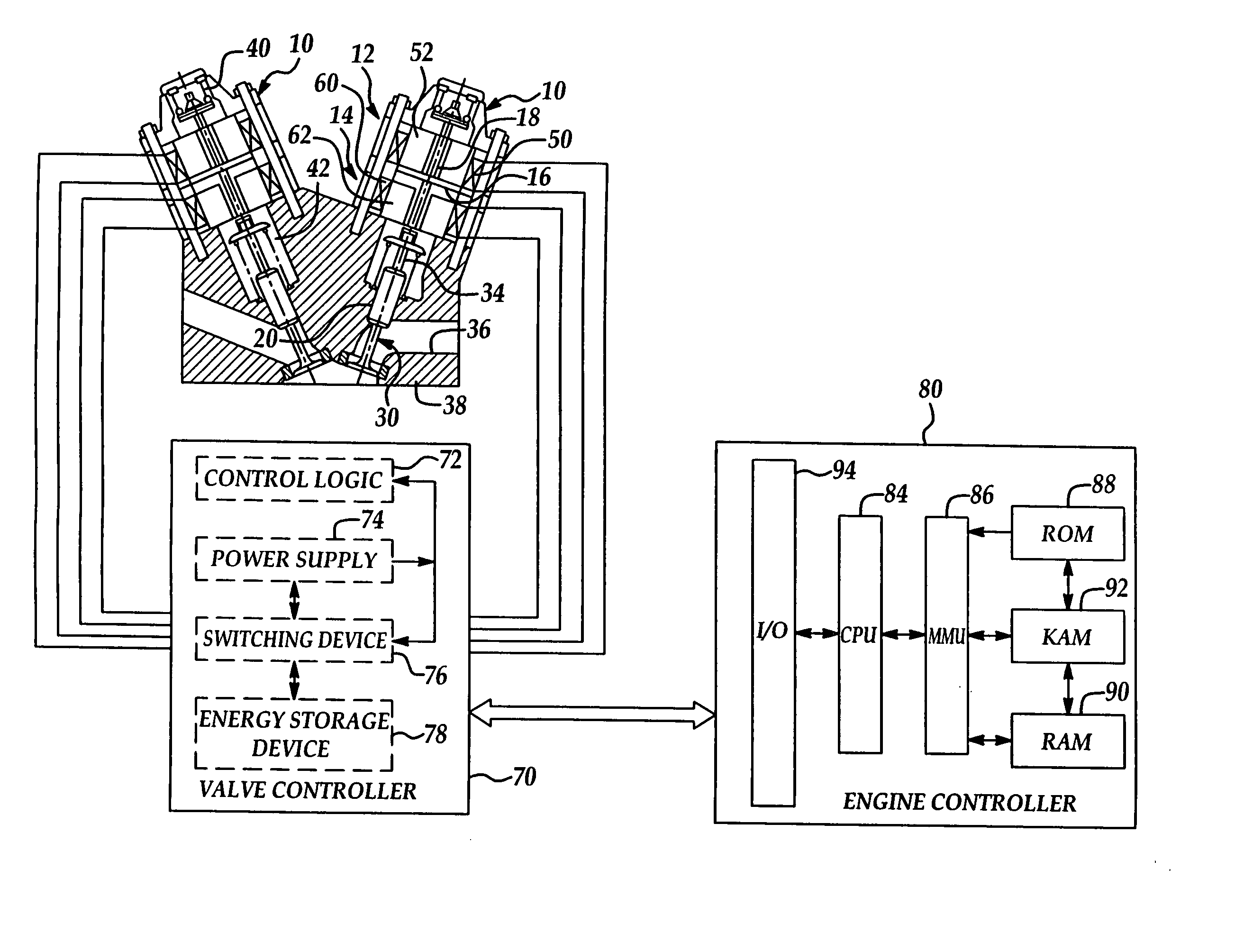
[0021] Referring now to the drawings wherein like reference numerals are used to identify similar components in the various views, FIG. 1 is a cross-section illustrating one embodiment of a valve actuator assembly for an intake or exhaust valve of an internal combustion engine according to the present invention. Valve actuator assemblies 10 include an upper electromagnet 12 and a lower electromagnet 14. As used throughout this description, the terms “upper” and “lower” refer to positions relative to the combustion chamber or cylinder with “lower” designating components closer to the cylinder and “upper” referring to components axially farther from the corresponding cylinder. Those of ordinary skill in the art will recognize that actuator assemblies 10 generally include similar components that function in a similar or identical manner but may be sized differently to operate intake or exhaust valves, for example. The present invention is independent of the particular type of valve ac...


PUM

PropertyMeasurementUnit
distanceaaaaaaaaaa
distanceaaaaaaaaaa
distanceaaaaaaaaaa

Abstract

Systems and methods for valve actuation use series-connected coils of upper and lower electromagnets acting as electromagnetic generators that attempt to maintain a constant magnetic flux, while their forces are essentially independent. A valve controller initiates valve actuation by reducing holding force of the holding electromagnet. As spring force begins to move an armature away from the holding electromagnet, the associated coil generates a voltage that attempts to maintain constant flux. This generated voltage causes a large increase in current that essentially transfers the flux to the other on-coming coil, which attracts and holds the armature against its associated spring force to open or close the valve. The internal voltage generated inside the two coils operates even if the coils are supplied with zero external voltage (shorted) to transfer stored energy directly between the coils. Energy may be transferred indirectly using an energy storage device.

Description

BACKGROUND OF THE INVENTION [0001] 1. Field of the Invention [0002] The present invention relates to a system and method for actuation of a valve, such as an intake and / or exhaust valve of an internal combustion engine. [0003] 2. Background Art [0004] Electromagnetic or electronic valve actuation (EVA) offers greater control authority and can significantly improve engine performance and fuel economy under various operating conditions relative to conventional camshaft arrangements. EVA systems use electromagnetic actuators to electrically or electronically open and close the intake and / or exhaust valves. [0005] Electromagnetic actuators controlled by an associated valve controller, engine controller, and / or vehicle controller may use electromagnets or solenoids to attract an armature that operates on the valve stem. In a typical electromagnetic actuator, two opposing electromagnets and associated springs are used to open and close an engine valve in response to the signals generated ...

Claims


Application Information

Patent Timeline
Patent Type & Authority Applications(United States)
IPC IPC(8): F01L9/20H01F7/123H01F7/18H01H47/00
CPCF01L9/04F01L2009/0436F01L2009/048H01F2007/1692H01F7/123H01F7/1816H01F7/1844F01L2800/00F01L2009/408F01L2009/2136F01L9/20
Inventor KOTWICKI, ALLAN J.
Owner FORD GLOBAL TECH LLC
Why Eureka
Try Eureka