
Image data compression device, encoder, electronic apparatus, and method of compressing image data

a compression device and encoder technology, applied in the field of image data compression devices, encoders, electronic devices, and methods of compressing image data, can solve the problems of not meeting the requirements of miniaturization of instruments, requiring a large circuit scale, and becoming difficult to miniaturize the ic, so as to reduce reduce the size of encoded data, and increase the size of quantized data

Inactive Publication Date: 2005-11-10
SEIKO EPSON CORP
View PDF1 Cites 13 Cited by
  • Summary
  • Abstract
  • Description
  • Claims
  • Application Information

AI Technical Summary

Benefits of technology

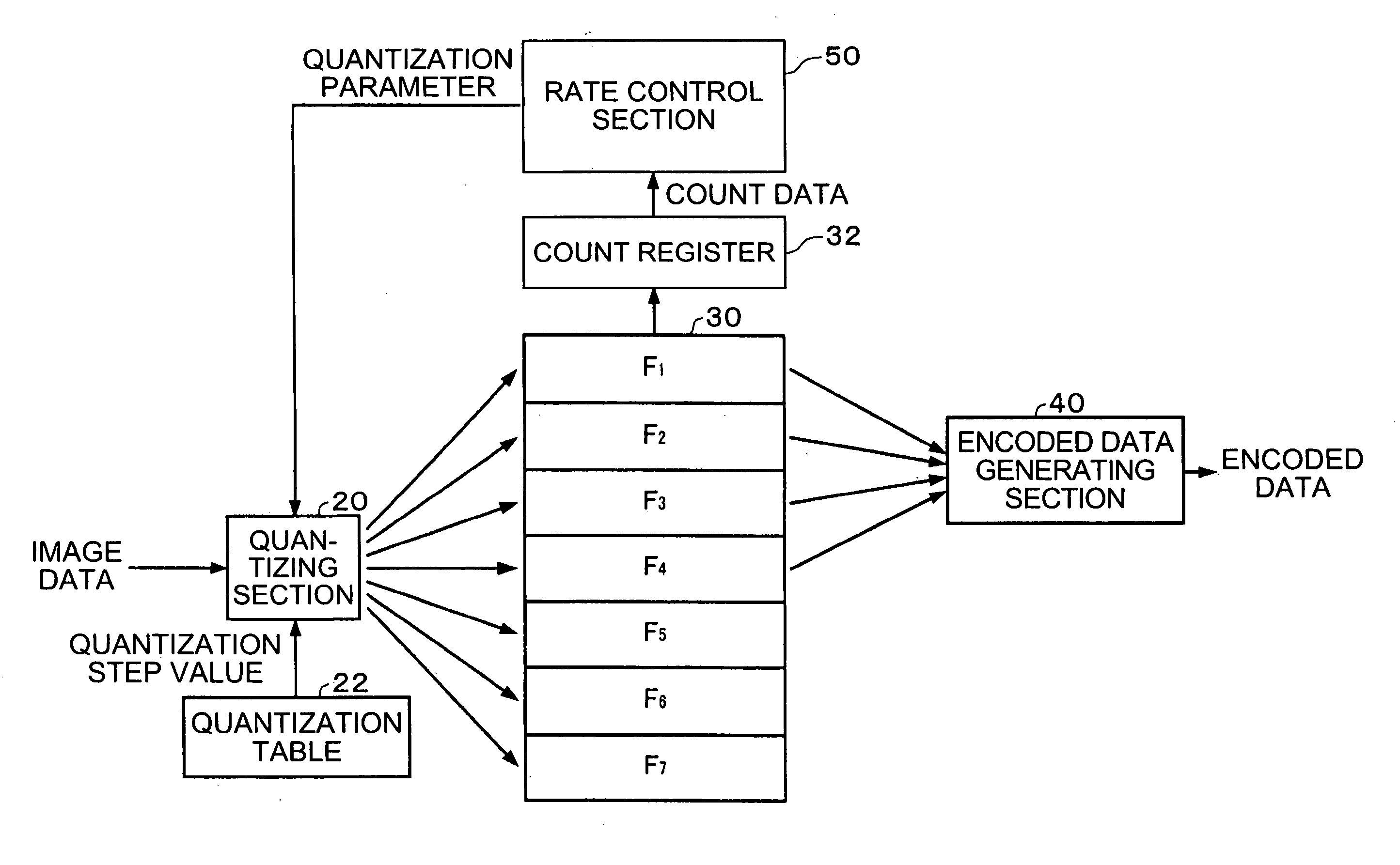
The present invention relates to an image data compression device that can control the data size of compressed image data. The device includes a quantizing section that quantizes image data with a quantization step changing for each frame. The device also includes an encoded data generating section that generates encoded data asynchronously with the quantization section. The rate control section controls the data size of the encoded data by changing the quantization step based on the predicted data size of the quantized data. This allows for constant bit rate encoding and prevents degradation of image quality. The device can also include a frame skipping section that skips the generating process of the image data to further reduce the size of the encoded data. The rate control section compares reference bit numbers and reference frame numbers to set or release the upper limit threshold of the quantization parameter. Overall, the device allows for efficient image data compression and maintains the bit rate while preventing degradation of image quality.

Problems solved by technology

However, in this case, a large circuit scale is required, and if the circuit is made as an IC (semiconductor device, integrated circuit), it becomes difficult to miniaturize the IC.
In particular, in portable instruments such as mobile phones, it cannot meet the requirement for miniaturization of the instruments.
However, in this case, a load on the CPU (Central Processing Unit) for executing the software is problematically increased.
Further, it causes the processing time to be increased, thus increasing power consumption.
In particular, in portable instruments such as mobile phones, it cannot meet the requirement for low power consumption for restricting consumption of the battery.
However, as a result of study by the present inventors, it has been revealed that, when considering the most effective way of sharing the series of encoding processes by hardware and software, the rate control method disclosed in the MPEG-4 Visual Part (Recommendation ISO / IEC 14496-2: 1999(E) L) cannot be put into practice.
However, it has been revealed that, if the buffer is provided, the rate control method cannot be executed, thus the optimization of assignment of image data compression process to hardware and software and generation of compressed data at a constant rate are problematically incompatible.
Further, even if the generation rate of the compressed data can be controlled, the rate control method described in the MPEG-4 Visual Part (Recommendation ISO / IEC 14496-2: 1999(E) L) often causes block noises displayed in the image obtained by expanding the compressed data, thus the display quality can problematically be degraded.
Meanwhile, the amount of the compressed data is increased in order to prevent degradation of the display quality, thus it is problematical that a predetermined bit rate may not be maintained.
In this case, if a large number of bits are used in the first half of the encoding process, the possibility of causing the bit rate overrun is increased, and it becomes difficult to maintain the predetermined bit rate.
Therefore, if the process with small amount of information and a light operational load is processed by the software processing section, the load of the process is still light.
On the contrary, most of the processes of the quantization have a large amount of information and require complicated operations, and accordingly, have too heavy load for software to process.
Further, since the amount of data after processed by the hardware processing section is small, the amount of data transmitted from the hardware processing section to the software processing section is small accordingly, the transmission load is also light.

Method used


Image

  • Image data compression device, encoder, electronic apparatus, and method of compressing image data
  • Image data compression device, encoder, electronic apparatus, and method of compressing image data
  • Image data compression device, encoder, electronic apparatus, and method of compressing image data

Examples


Embodiment Construction

[0091] Hereinafter, an embodiment of the present invention is described in detail with reference to the accompanying drawings. Note that the embodiment described below does not unreasonably limit the content of the present invention as claimed in the claim section. Further, not all of the components of the configuration described below are essential elements of the present invention.

[0092] 1. MPEG-4

[0093] Firstly, an encoding process of the MPEG-4 will be briefly described. Further, a decoding process for expanding the compressed data encoded with the encoding process will also be described.

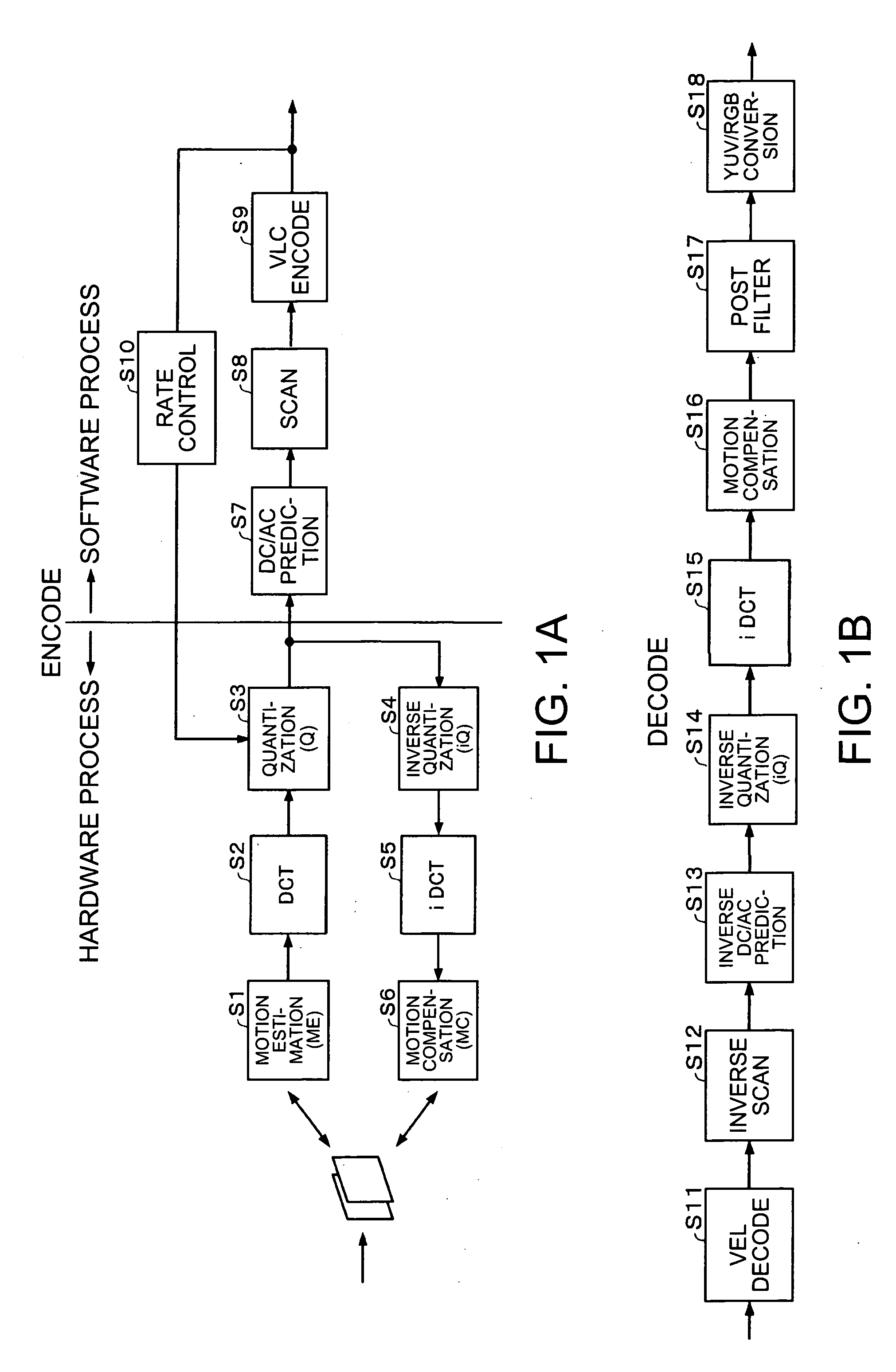
[0094]FIGS. 1A and 1B show views for explaining the encoding process and the decoding process of the MPEG-4. Since details of the processes are explained in, for example, “JPEG & MPEG, image compression technology easily comprehensible with illustrations” (co-authored by Hiroshi Ochi and Hideo Kuroda) published by Nippon Jitsugyo Publishing Co. Ltd., only the process relating to the present in...


PUM


Abstract

An image data compression device comprises a quantizing section for quantizing image data with a quantization step changing in accordance with a quantization parameter, a FIFO buffer section for buffering the quantized data corresponding to a plurality of frames, an encoded data generating section for generating encoded data obtained by encoding the quantized data retrieved from the FIFO buffer section asynchronously with writing thereto, and a rate control section for controlling a data size of the encoded data by changing the quantization step. The rate control section finds a predicted data size of the encoded data of the precedent frame from the size of the quantized data of the precedent frame, and sets or releases an upper limit threshold of the quantization parameter based on the number of assignable bits assignable to a compressing process or the number of remaining frames. When setting the upper limit threshold of the quantization parameter, the quantization parameter is found so as to be equal to or less than the upper limit threshold of the quantization parameter using the predicted data size.

Description

RELATED APPLICATIONS [0001] This application claims priority to Japanese Patent Application No. 2004-139755 filed May 10, 2004 which is hereby expressly incorporated by reference herein in its entirety. BACKGROUND [0002] 1. Technical Field [0003] The present invention relates to an image data compression device, an encoder, an electronic apparatus, and a method of compressing image data. [0004] 2. Related Art [0005] As a general purpose encoding method for multimedia information such as image data of static images or moving images or voice data, MPEG-4 (Moving Picture Experts Group Phase 4) has been standardized. Portable instrument of recent years is capable of realizing encoding and decoding of image data compliant with the MPEG-4 standard to reproduce moving images or to communicate the moving images through a network. [0006] According to the MPEG-4 standard, compressed data obtained by encoding image data of a moving image need to be generated at a constant rate. However, when c...

Claims


Application Information

Patent Timeline
Patent Type & Authority Applications(United States)
IPC IPC(8): H04N19/50H03M7/30H04N7/12H04N19/126H04N19/132H04N19/14H04N19/149H04N19/196H04N19/42H04N19/423H04N19/513H04N19/60H04N19/625H04N19/85H04N19/91
CPCH04N19/176H04N19/172H04N19/149H04N19/152H04N19/124H04N19/132H04N19/61
Inventor KONDO, YOSHIMASAOSADA, KYOICHI
Owner SEIKO EPSON CORP
Learn More