[0005] The arrangement of the present invention provides an efficient solution to the problems with the current designs of bone anchored hearing aid couplings. More specifically, the arrangement of the present invention includes a mechanical control arm
system where the coupling force is counteracted in a way that the connection and disconnection of the hearing aid can be done without any force loading the fixture and the abutment. In this way, it is possible for the patient to start to use the hearing aid before the fixture is fully integrated in the bone which takes around 3-6 months, hence the patient will be rehabilitated much quicker. If the fitting is done in conjunction with the
insertion of the fixture also a lot of costs for both patients and the health care
system can be saved since this means the patients, who might have to travel long distances to the hospital, do not need to come back for an extra appointment to do the hearing aid fitting. The arrangement of the present invention also provides advantages for patients having a
poor fixation of the fixture in the skull due to for example poor
bone quality where the arrangement of the present invention can offer a minimal stress on the fixture in the bone. Another
patient group in need for the arrangement of the present invention is
small children where the
skull bone is very soft. There are also patients who would prefer a coupling with control arms simply because they do not feel comfortable with the high forces that need to be applied when taking the device on and off. If the control arm
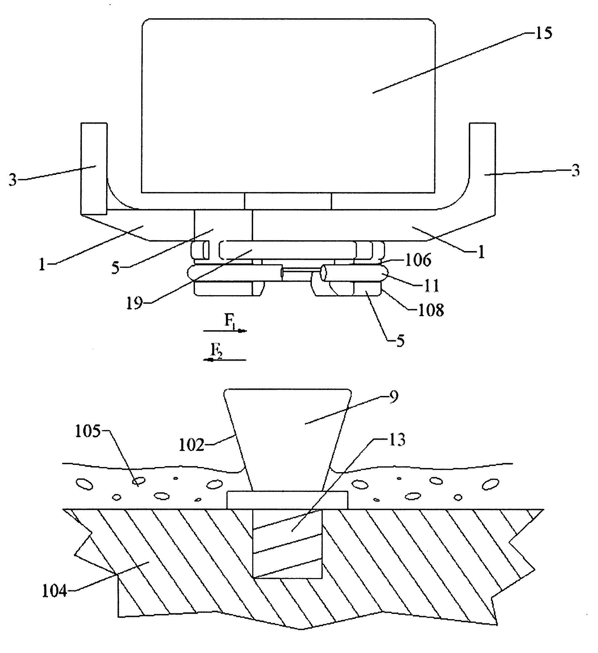
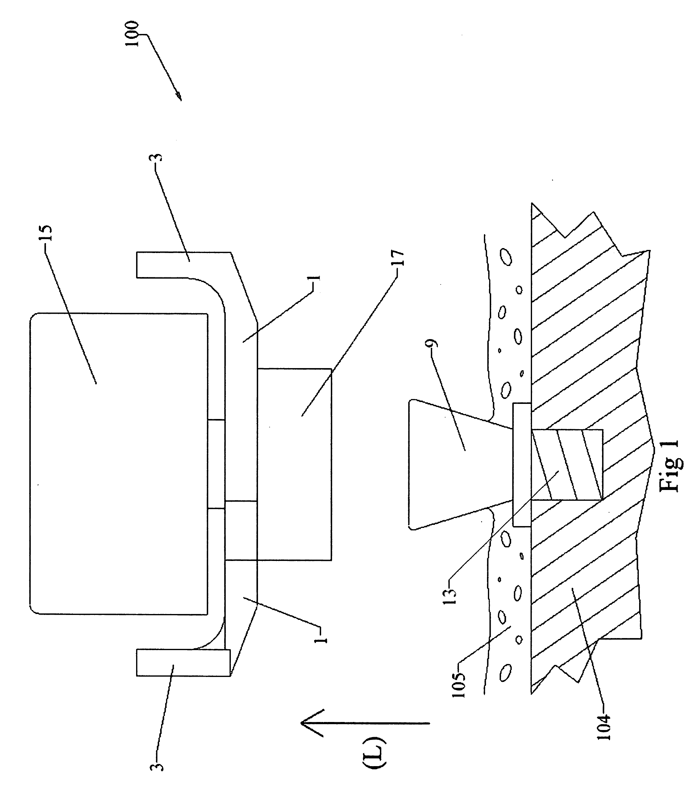
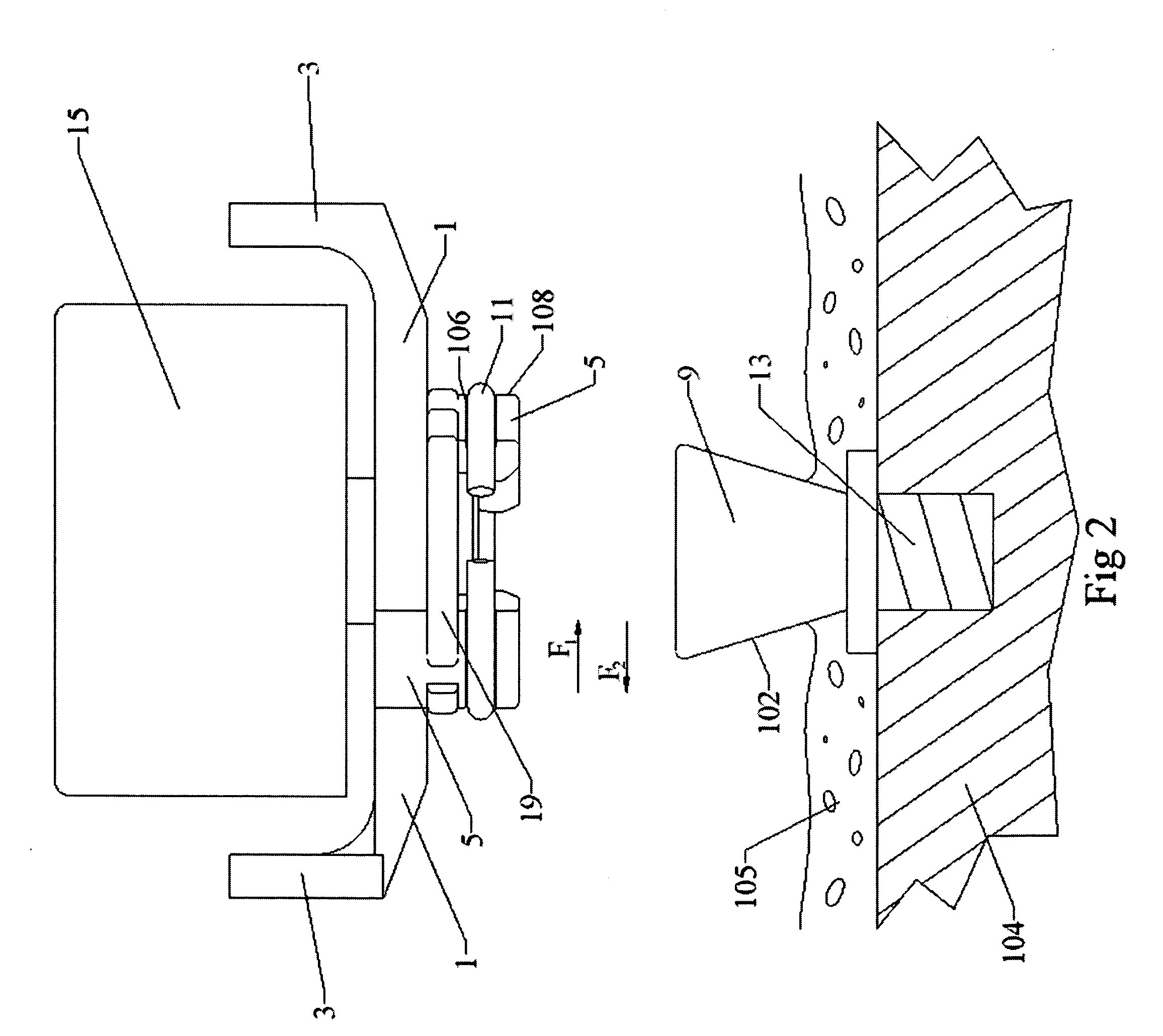
system is used this will not only lower the stress on the fixture and the abutment but also on the hearing aid, hence the hearing aid will last longer. The control arm extends from a
handle to the connection and transfers the force from the patients' fingers to the connection where the force is used for counteracting a coupling force in the connection. The arrangement of the present invention can have one or more control arms. The biasing means, generating the coupling force and / or counteracting the force on the handle on the control arm, may, for example, be a spring, an O-ring, a
magnet or a flexible material.
[0011] In case of a
magnetic interaction between the connection and the abutment another preferred embodiment includes a sleeve on the connector that goes either around the outside of the abutment or inside of the abutment to avoid the magnetic coupling shoe from sliding off the abutment in radial direction. Without the connector sleeve a significantly stronger
magnet would have been required to prevent the hearing aid from falling off. In this arrangement the control arm can be connected to the coupling sleeve. The coupling sleeve is moved in lateral direction in such a way that the magnetic coupling shoe can be moved freely in radial direction in relation to the abutment when a force is applied on the handle. By sliding the magnetic connector in radial direction the forces on the fixture may be significantly reduced compared to when pulling the connector away from the abutment in lateral direction. This arrangement only limits the force when disconnecting the abutment from the connector and does not limit the force when connecting the abutment to the connector. This may however be a cost efficient and sufficiently good arrangement for some patients.
[0020] For any off the above arrangements several different designs of a control arm is possible. Specifically the control arm can also be designed as a turning wheel. One practical
advantage of the wheel design is that the user is less likely to inadvertently turn the handle by hitting something since there is no protruding part. The wheel is also symmetrical so that it is suitable both for left and right ears.

