Mesh based frame processing and applications

a frame processing and mesh technology, applied in image data processing, television systems, instruments, etc., can solve the problems of reducing the effectiveness of the mesh-based motion analysis model, the inability to accurately estimate the motion accuracy of the block matching model, and the inability to accurately represent the inter-frame dynamics related to the reshaping of video objects, so as to reduce the computational cost

Active Publication Date: 2005-11-10
INTELLIVIEW TECH
View PDF16 Cites 81 Cited by
  • Summary
  • Abstract
  • Description
  • Claims
  • Application Information

AI Technical Summary

Benefits of technology

[0013] An aspect of the invention includes a motion-based object detection and tracking algorithm. According to this aspect of the invention, a method of processing a frame of date involves extracting object feature points (tracking points) and constructing an affine-based model to predict the size and position of an object during the tracking process. Affine models are zoom invariant, which mak

Problems solved by technology

However, the block matching model has major limitations in the accuracy of estimated motion, since it only allows inter-frame dynamics to be described as a series of block translations.
As a result, any inter-frame dynamics related to the reshaping of video objects will be inaccurately represented.
The efficacy of the mesh-based motion analysis model, even with the improvements disclosed in this patent document, is often limited by the domain disparity between the affine transform function and the pel domain.
In particular, since the affine transform is a continuous mapping function while the pel domain is discrete in nature, a discretization error will result when the affine transform is applied to the pel domain.
As pel values are not uniformly distributed in a video frame,

Method used


Image

  • Mesh based frame processing and applications
  • Mesh based frame processing and applications
  • Mesh based frame processing and applications

Examples


embodiment

Features

[0106] An advantage of this embodiment is that one module can be designed for both fixed and PTZ cameras. A basic system may include such features as basic monitoring and analysis, signal control, incident recording and networking. New features, such as vehicle tracking, red light enforcement, system-level control, etc., can be added later via software upgrades that can be obtained, for example, by downloading them over the network. The following table defines possible basic and expanded features:

Fixed IntersectionHighway PTZCameraCameraBasic FeaturesMonitoring & analysisXXIncident recordingXXWireless networkXXImage enhancementXXSignal controlXExpanded FeaturesSystem-level controlXVehicle trackingXZoningXEnforcementX

[0107] Monitoring and analysis can include traffic volume, density, lane occupancy, classification of vehicles, or road conditions in a lane. Signal control can include the presence of vehicles approaching or waiting at an intersection, queue length measurement...


PUM


Abstract

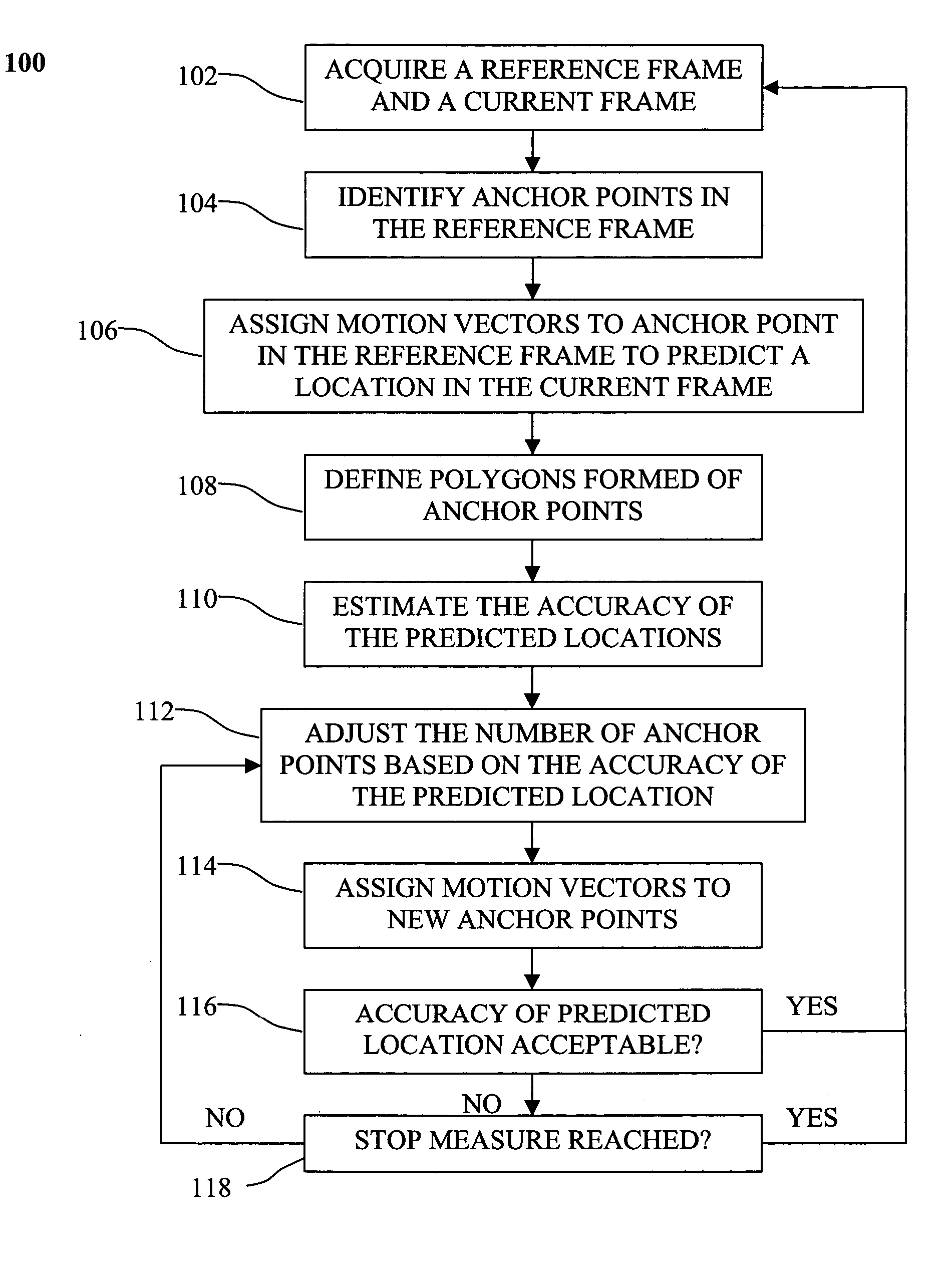
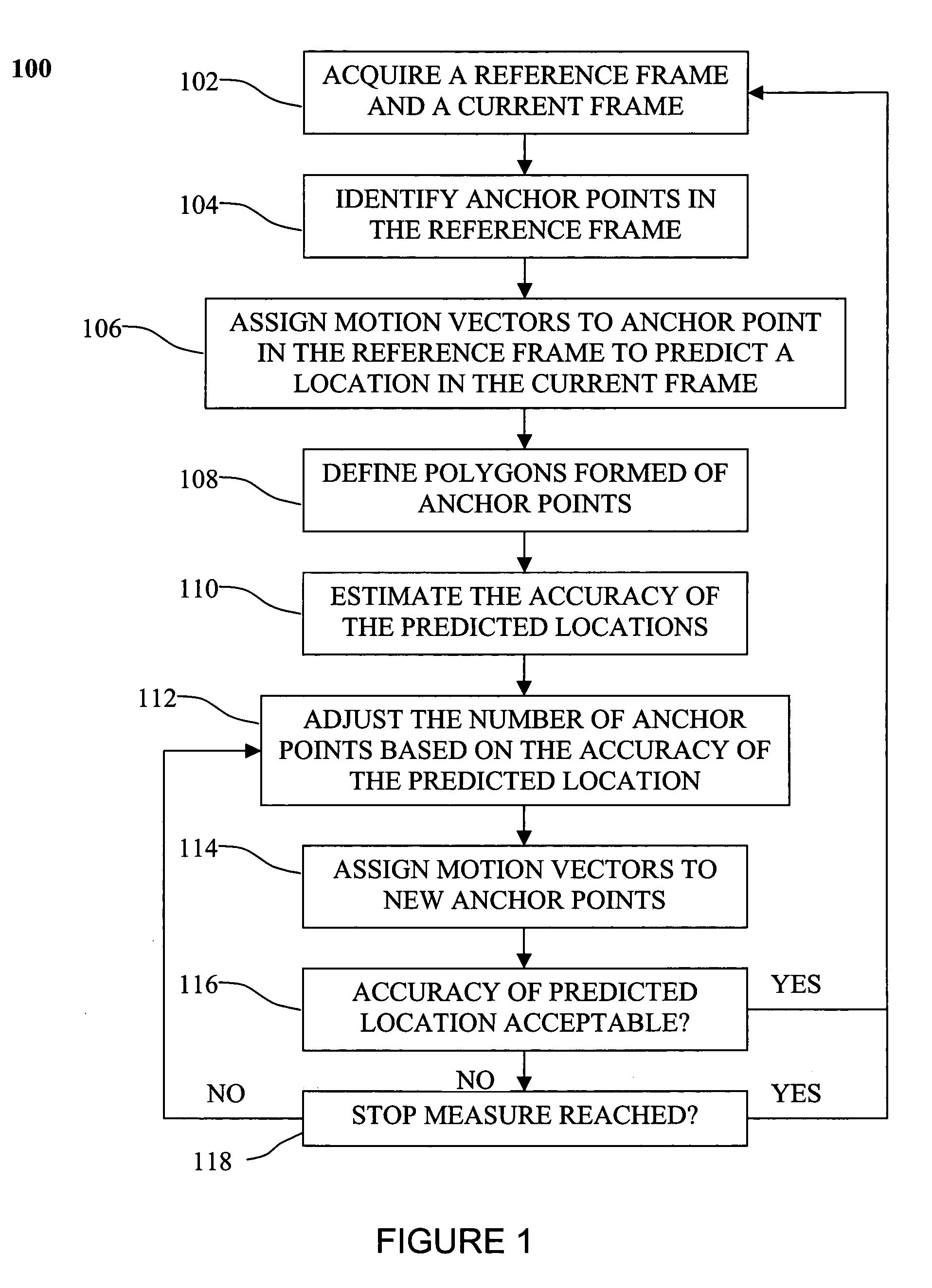
A method of processing sequential frames of data comprises repeating the following steps for successive frames of data: acquiring at least a reference frame containing data points and a current frame of data points; identifying a set of anchor points in the reference frame; assigning to each anchor point in the reference frame a respective motion vector that estimates the location of the anchor point in the current frame; defining polygons formed of anchor points in the reference frame, each polygon containing data points in the reference frame, each polygon and each data point contained within the polygon having a predicted location in the current frame based on the motion vectors assigned to anchor points in the polygon; for one or more polygons in the reference frame, adjusting the number of anchor points in the reference frame based on accuracy of the predicted locations of data points in the current frame; and if the number of anchor points is increased by addition of new anchor points, then assigning motion vectors to the new anchor points that estimate the location of the anchor points in the current frame.

Description

BACKGROUND OF THE INVENTION [0001] The recent advance in the field of communication-based applications such as videophone and video conferencing systems mainly concentrate on minimizing the size and the cost of the coding equipment. The low cost of the final product is the most essential part of the current age of technology. Most current real-time systems include video applications that need to process huge amounts of data and large communication bandwidth. Real-time video applications include strategies to compress the data into a feasible size. [0002] Among different data compression techniques, object-based video representation, as addressed by MPEG-4, allows for content-based authoring, coding, distribution, search and manipulation of video data. In MPEG-4, the Video Object (VO) refers to spatio-temporal data pertinent to a semantically meaningful part of the video. A 2-D snapshot of a Video Object is referred to as a Video Object Plan (VOP). The 2-D triangular mesh is designed...

Claims


Application Information

Patent Timeline
IPC IPC(8): G06K9/00G06K9/36H04N7/26H04N7/50
CPCG06T9/001H04N19/597H04N19/176H04N19/61H04N19/54H04N19/137H04N19/20H04N19/527H04N19/12
Inventor BADAWY, WAEL
Owner INTELLIVIEW TECH
Why Eureka
Try Eureka