Shockwave-induced boundary layer bleed

a boundary layer and shock wave technology, applied in the direction of motors, engine control, air transportation, etc., can solve the problems of blade stall, complete compressor surging, separation of airflow on the compressor blades, etc., and achieve the effect of improving efficiency

Active Publication Date: 2005-11-10
PRATT & WHITNEY CANADA CORP
View PDF25 Cites 18 Cited by
  • Summary
  • Abstract
  • Description
  • Claims
  • Application Information

AI Technical Summary

Benefits of technology

[0005] It is an aim of the present invention to provide a

Problems solved by technology

Increased incidence angle between the airflow and the blade leading edges at “off design” conditions tends to cause separation of the flow on the suction side of the blades, which results in blade stall and eventually complete surging of the compressor.
However, separation of airflow on the compressor blades can also result from factors other than increased blade leading edge incidence.
Particularly, the interaction between the boundary layer formed on

Method used


Image

  • Shockwave-induced boundary layer bleed
  • Shockwave-induced boundary layer bleed
  • Shockwave-induced boundary layer bleed

Examples


Embodiment Construction

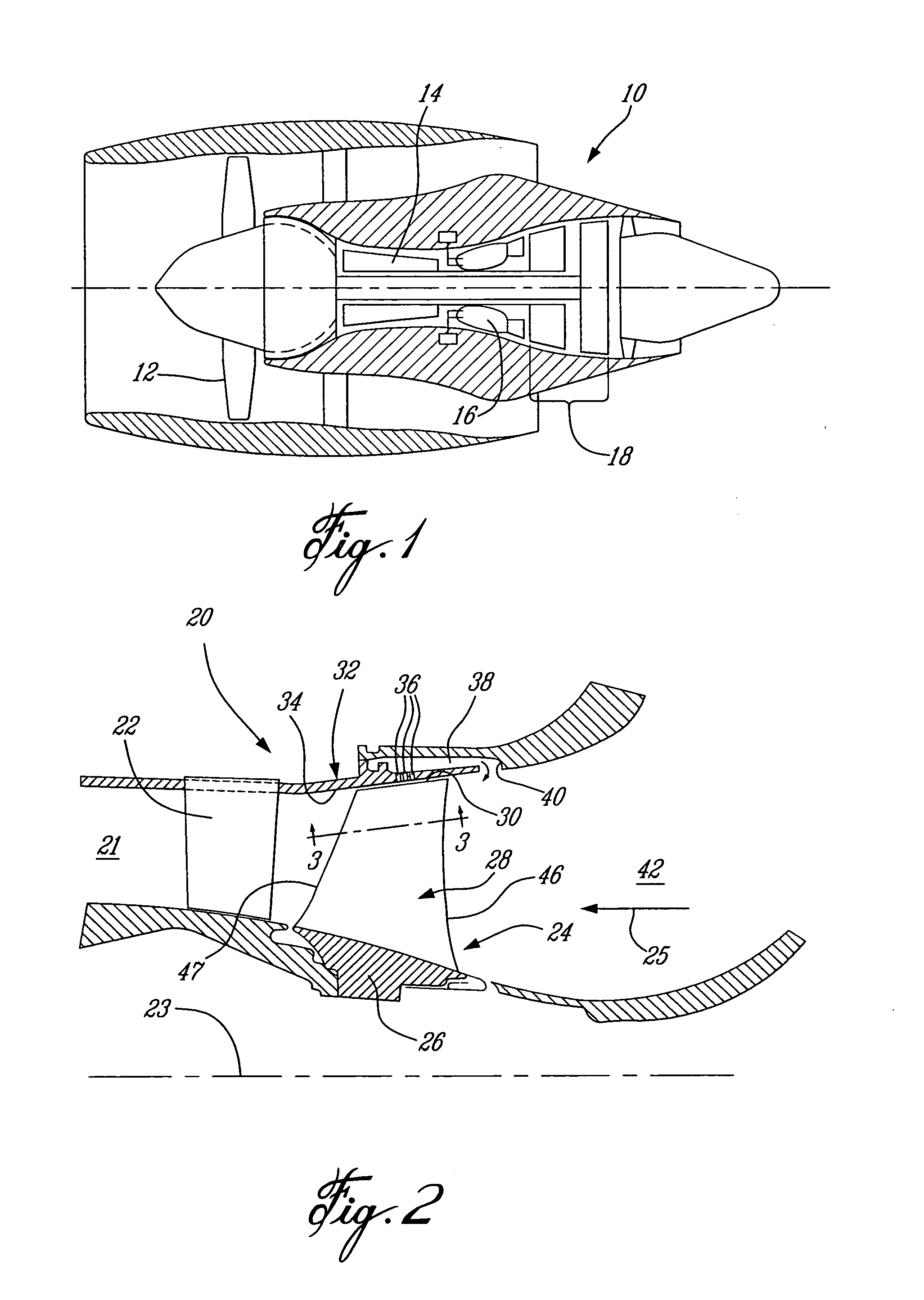
[0015]FIG. 1 illustrates a gas turbine engine 10 of a type preferably provided for use in subsonic flight, generally comprising in serial flow communication a fan 12 through which ambient air is propelled, a compressor section 14 for pressurizing the air, a combustor 16 in which the compressed air is mixed with fuel and ignited for generating an annular stream of hot combustion gases, and a turbine section 18 for extracting energy from the combustion gases.

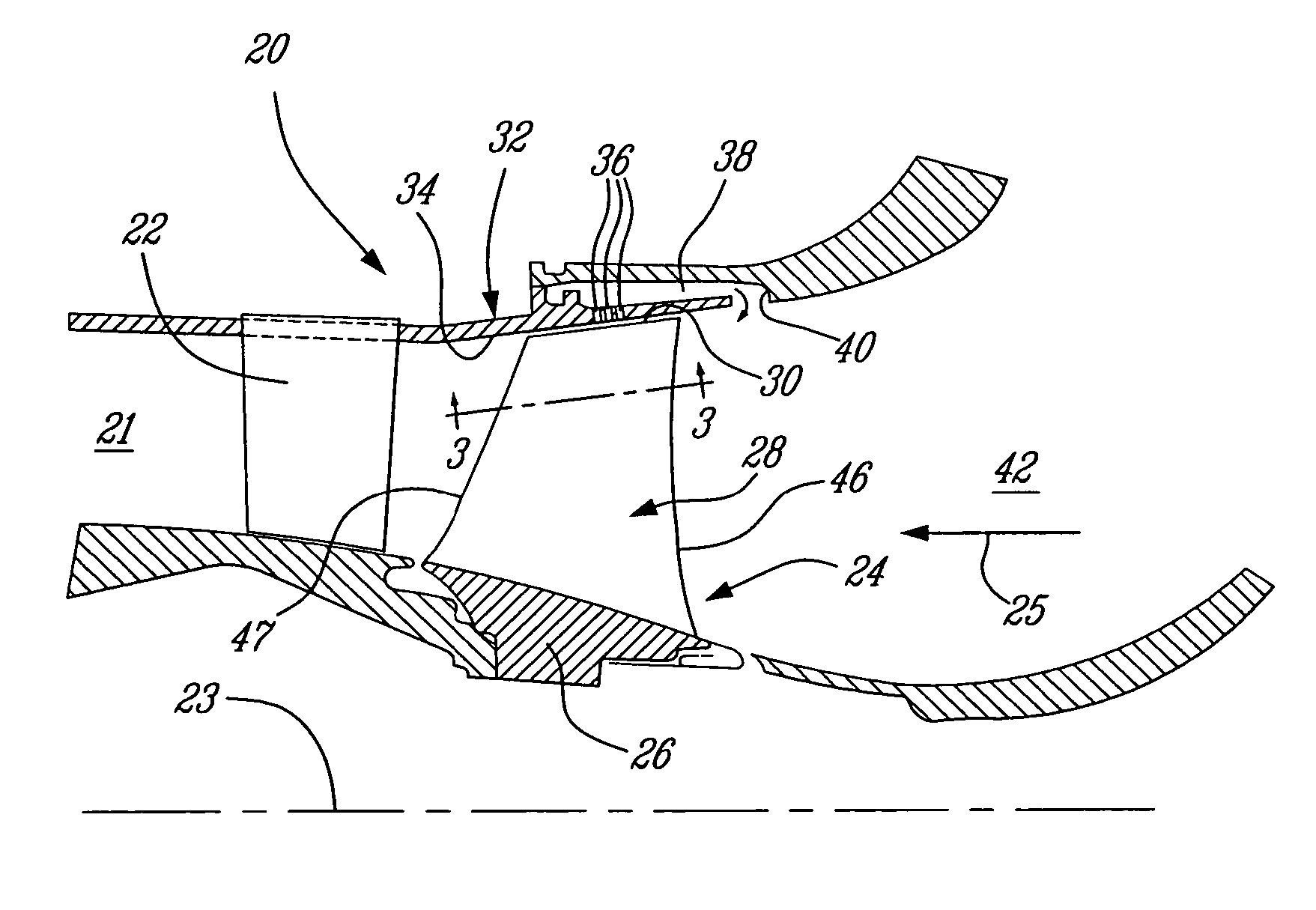
[0016] The compressor section 14 is typically a multi-stage compressor, and thus may comprise several axial and / or centrifugal compressors. Although the present invention is preferably adapted for use with an axial turbomachine rotor, and will therefore be described below with regards to its use in an axial compressor, it is to be understood that the use of the present invention in a centrifugal compressor and / or a mixed flow rotor is also envisaged. The present invention is also intended for transonic compressor rotors rather th...


PUM


Abstract

An apparatus and method is provided for improving efficiency of a transonic gas turbine engine compressor by bleeding off a shockwave-induced boundary layer from the gas flow passage of the compressor using an array of bleed holes having a downstream edge aligned with a foot of an oblique shock wave which originates on the leading edge of an adjacent transonic rotor blade tip.

Description

TECHNICAL FIELD [0001] The present invention relates generally to gas turbine engines, and more particularly to an improved compressor therefor. BACKGROUND OF THE INVENTION [0002] Bleeding air from gas turbine engine compressors is well known. Air bled from the compressor can sometimes be used to provide a source of pressurized and / or cool air to the engine or the aircraft, however air is principally bled from the compressor in order to improve the operating envelope and overall compressor efficiency, which is often expressed as improved surge margin. Increased incidence angle between the airflow and the blade leading edges at “off design” conditions tends to cause separation of the flow on the suction side of the blades, which results in blade stall and eventually complete surging of the compressor. By bleeding off this stalled airflow adjacent the blade tips, the surge margin of the compressor is thus increased. This accordingly improves the overall efficiency of the compressor. [...

Claims


Application Information

Patent Timeline
IPC IPC(8): F01D1/00F01D5/14F01D5/18F02C3/06F02C9/18F04D21/00F04D29/68
CPCF01D5/145F04D21/00Y10S415/914F05D2270/17Y02T50/673F04D29/681F04D29/526Y02T50/60F04D29/685F04D29/682
Inventor LEBLANC, ANDRE DENISOUELLET, GILBERT
Owner PRATT & WHITNEY CANADA CORP
Why Eureka
Try Eureka