Electromechanical lock employing shape memory metal wire

a technology of electromechanical locks and metal wires, applied in the field of electromechanical locks, can solve the problems of high power consumption, inability to make conventional electromagnetic devices small to a certain degree, and the feebleness of the metal wires produced by them,

Inactive Publication Date: 2005-11-17
NANOTECH
View PDF9 Cites 54 Cited by
  • Summary
  • Abstract
  • Description
  • Claims
  • Application Information

AI Technical Summary

Benefits of technology

[0010] A better solution, as presented in the present invention, is to get rid of the tension spring. Not only anchoring the shape memory metal wire directly or non-elastically to the background or components of sizable bulk of the lock is much easier than to a tension spring, controlling the amount of stretching of the shape memory metal wire at low temperature to a certain percentage of its total length is quite straightforward.

Problems solved by technology

Besides having the usual drawbacks of high power consumption, susceptibility to vibration and external magnetic field (electromagnet and solenoid), these conventional electromagnetic devices can only be made small to a degree before forces produced by them become too feeble to be useful.
Furthermore, manufacturing of ever smaller electromagnetic devices soon becomes prohibitively costly.
Worse yet, if they are used in a stand-alone, battery-powered electromechanical lock, battery life would be unacceptably short.
There are two problems with this arrangement.
First, soldering or welding cannot be used to join the shape memory metal wire to the spring because heat from the process would destroy the shape memory metal wire.
At such tiny scale it is extremely difficult, if not impossible, to perform such joining.
Second, even though shape memory metal wire can be stretched as much as 8% at low temperature and subsequently recovers when heated, it would fail to function after a relatively few, e.g. under 100, cycles.
Such increase in contraction and force makes it necessary to use longer and thicker shape memory metal wire, which takes up more room and consumes more energy.

Method used


Image

  • Electromechanical lock employing shape memory metal wire
  • Electromechanical lock employing shape memory metal wire
  • Electromechanical lock employing shape memory metal wire

Examples


Embodiment Construction

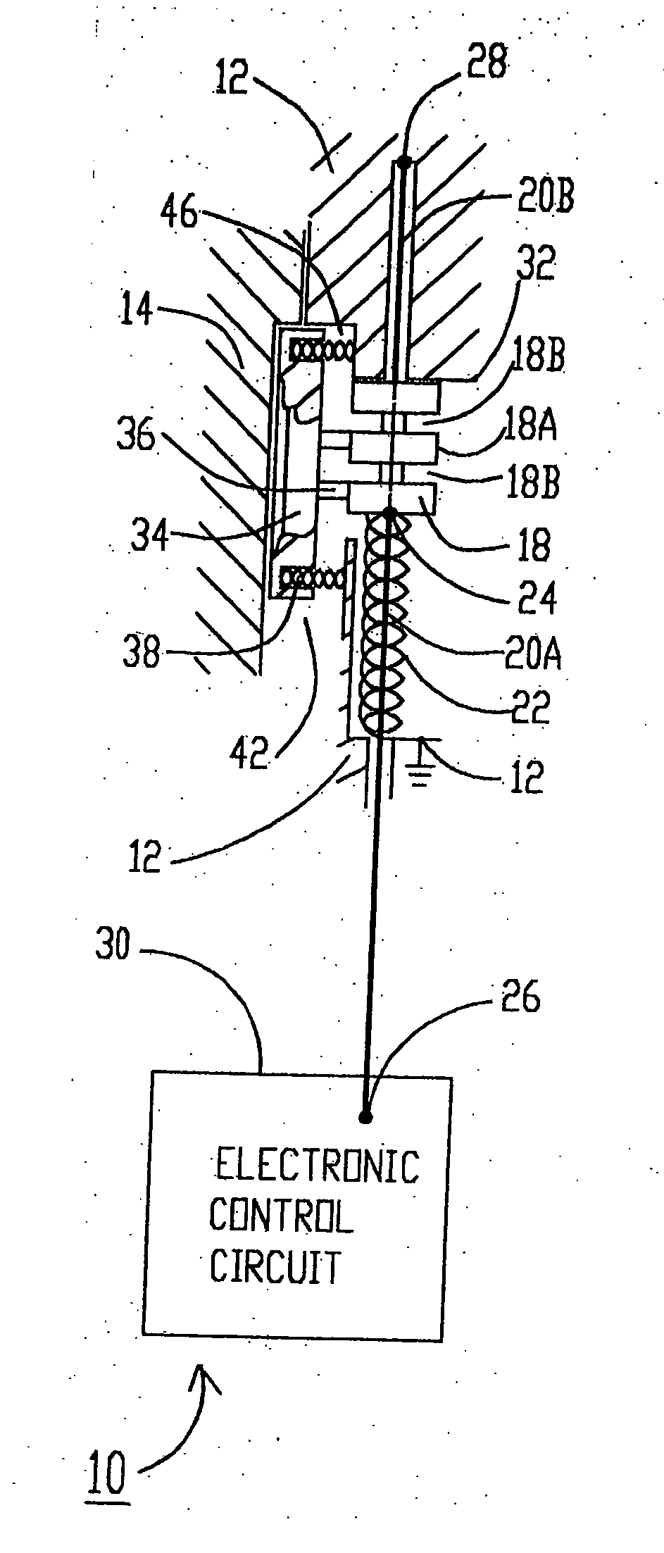
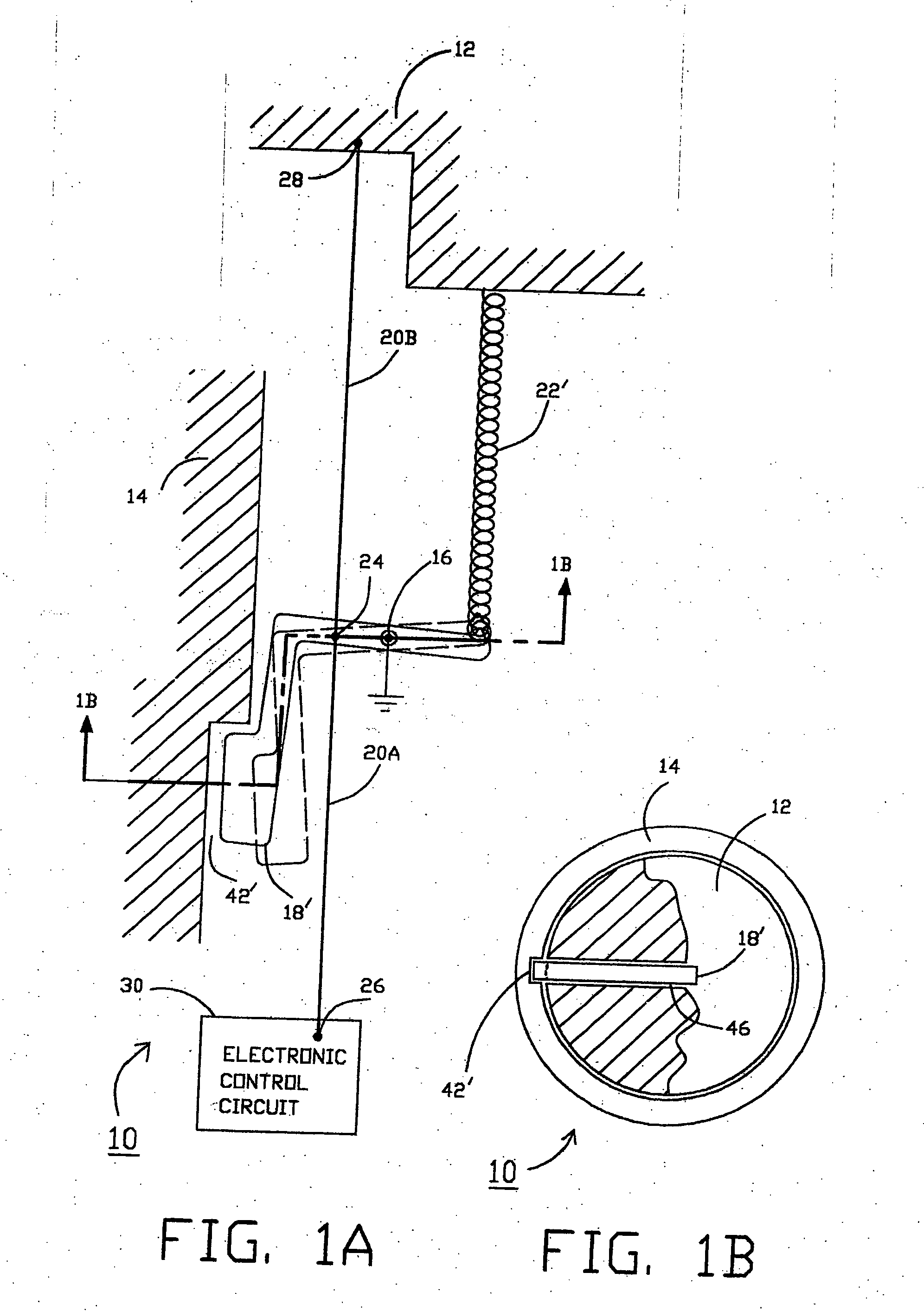
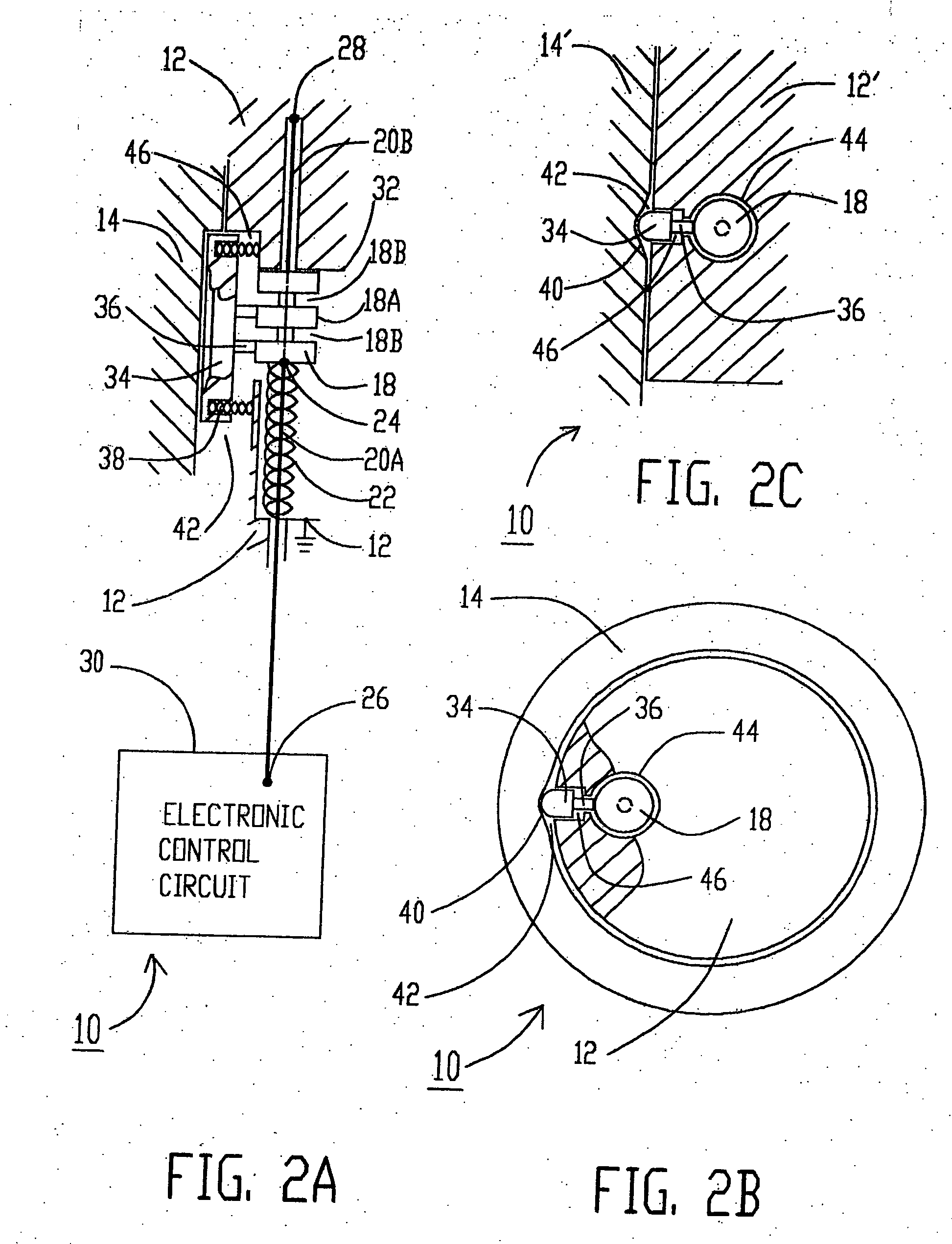
[0026] Referring to FIGS. 1A and 1B, the preferred embodiment of the electromechanical lock takes the form of a common mechanical lock cylinder 10 comprising shell 14 and plug 12. Shell 14 and plug 12 both are connected to electrical ground. Electrically conductive gate 18′ is disposed inside plug 12 with electrically conductive gate pivot 16. Gate 18′ is urged on one side by mechanical biasing means 22′, such as a spring, and is connected on the other side through attaching means 24, such as an eyelet, to shape memory metal wire 20, comprising wire segments 20A and 20B, preferably at or around the midpoint of wire 20, at the junction between the two segments. Shape memory metal wire segment 20A is connected at its other end through attaching means 26, such as an eyelet, to electronic control circuit 30. Shape memory metal wire segment 20B at its other end is anchored in the opposite direction to plug 12 by attaching means 28, such as an eyelet. Depending on what is required, the va...


PUM


Abstract

An electronic lock incorporating one or more shape memory metal wire segment as its electromechanical transducer. An electronic control circuit injects electrical current into the shape memory metal wire, causing it to heat up and contract. A gate is positioned by the action of the shape memory metal wire(s) to either allow or block the movement of a locking bolt that affect locking or unlocking. Millions of operational cycles are achieved by limiting the stretching of the shape memory metal wire at low temperature to small percentages of its total length. The design lends itself to miniaturization, with commensurate reduction in power consumption, that is useful to the evolution of future electronic locks.

Description

CROSS-REFERENCE TO RELATED APPLICATION [0001] This application is a non-provisional application and claims the benefit of Application No. 60 / 570,847, filed May 12, 2004, which application is incorporated herein in its entirety by this reference.FIELD OF THE INVENTION [0002] The present invention relates generally to an electromechanical lock and in particular an electromechanical lock incorporating shape memory metal wire as the electromechanical transducer. BACKGROUND OF THE INVENTION [0003] Unlike most other electronic products, electronic locks must be exceedingly rugged to withstand severe physical abuse. This prerequisite imposes a lower limit beyond which critical mechanical components can no longer be arbitrarily made smaller. For reliable performance, forces driving these mechanical components necessarily must have large safety margins. Most existing electromechanical locks employ as transducers electromagnetic devices such as electromagnets, solenoids or motors to translate...

Claims


Application Information

Patent Timeline
Patent Type & Authority Applications(United States)
IPC IPC(8): E05B47/06E05B53/00E05B63/14E05B65/36
CPCE05B47/0009E05B63/14E05B47/0634E05B47/063Y10T70/7068Y10T70/60Y10T70/7102Y10T70/70
Inventor CHU, JOHN WUN-SING
Owner NANOTECH
Why Eureka
Try Eureka