
Infrared detection of solar cell defects under forward bias

a solar cell and forward bias technology, applied in the field of solar cell arrays, can solve the problems of inability to repair defective cells, failure of completed modules, and inability to meet the requirements of environmental sealing construction, so as to avoid the cost of assembly of non-functional (or low efficiency) modules

Inactive Publication Date: 2005-11-17
SPIRE
View PDF4 Cites 99 Cited by
  • Summary
  • Abstract
  • Description
  • Claims
  • Application Information

AI Technical Summary

Benefits of technology

[0006] The invention permits detection of defects such as microcracks, chipped cells, alignment errors and / or defective or missing solder joints, before module assembly and encapsulation. By providing quality assurance at this stage, the costs associated with assembly of non-functional (or low efficiency) modules can be avoided.

Problems solved by technology

The need for highly reliable and weather resistant modules has lead to environmentally sealed constructions that require significant expense to assemble.
Unfortunately, completed modules can sometimes fail, or operate in a sub-optimal manner, due to structural defects in one or more individual cells or in the wiring of such cells together.
Often these faults are not detected until after encapsulation, when repair of defective cells is no longer possible.

Method used


Image

  • Infrared detection of solar cell defects under forward bias
  • Infrared detection of solar cell defects under forward bias

Examples


Embodiment Construction

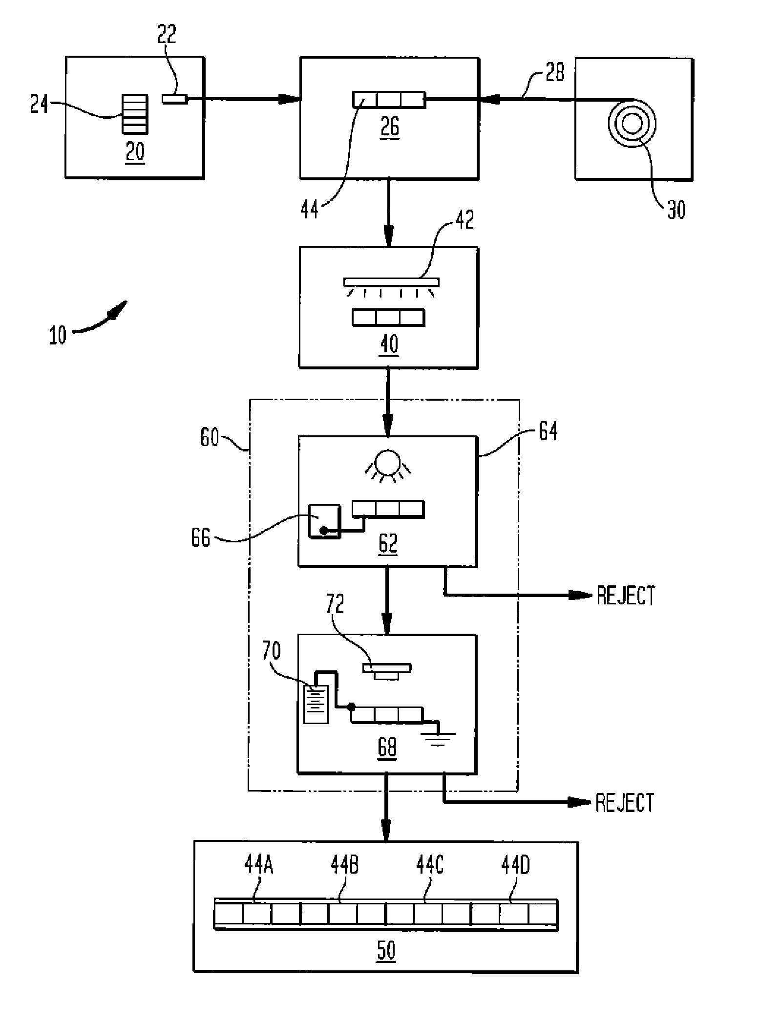
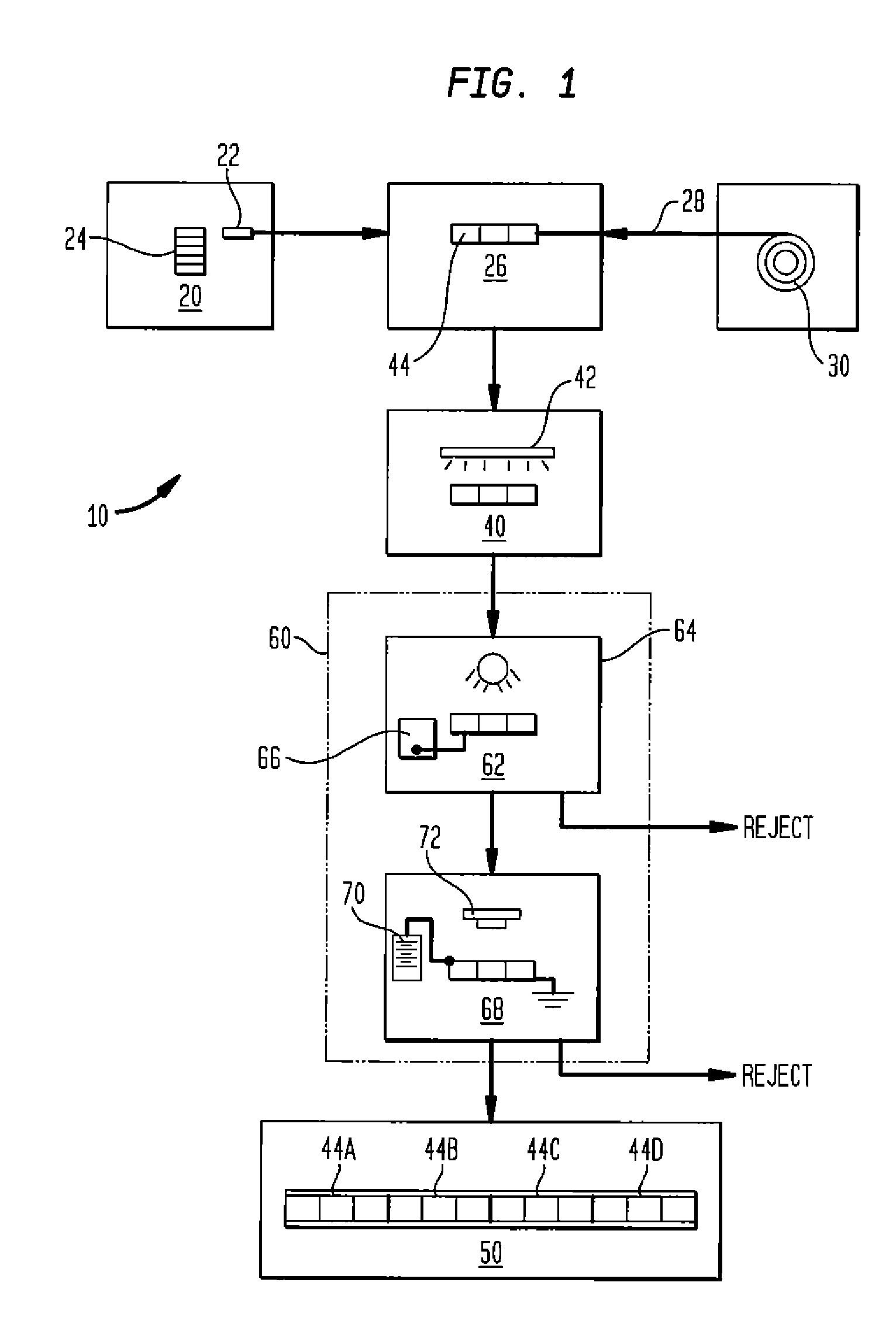
[0008] In FIG. 1 an automated solar cell module production system 10 interconnects solar cells 22 by soldering flat metal leads, or tabs, to cell contacts. The system 10 can process solar cells at a high-throughput, e.g., over 500 cells per hour, resulting in substantial cost savings in high volume production. In an initial cell alignment assembly 20, solar cells 22 are unloaded from stacks 24 and edge-aligned with a mechanical aligner 26. Tab material 28 is fed from reels 30, coated with flux, cut to length, and preferably provided with a stress-relief bend. Tabs 28 and cells 22 are aligned for soldering in a solder head assembly 40. High-intensity lamps 42 in the solder head assembly 40 provide radiant thermal energy to the cell and tabs. Both front and back cell contacts can be soldered in a single heating step to form a solar cell string 44.

[0009] A variety of solar cell sizes and shapes can be processed. The number of cells per string, the number of strings per module, and the...


PUM


Abstract

Methods and apparatus are disclosed for detecting solar cell defects by applying a forward-biasing electric current through a silicon solar cell or a group of interconnected solar cells for a short duration and then analyzing the resulting thermal image of each cell with an infrared (IR) camera. The invention is particularly useful in assembling solar cell arrays or modules in which large numbers of cells are to be wired together. Automated module assemblers are disclosed in which the cells (or strings of cells) are tested for defects prior to final module assembly.

Description

STATEMENT REGARDING FEDERALLY SPONSORED RESEARCH OR DEVELOPMENT [0001] The U.S. government has rights in this invention pursuant to contract awarded by the National Renewal Energy Laboratory, Contract No. ZDO-3-306628-12. This invention concerns solar cell arrays and, in particular testing of solar cells and solar cell subassemblies prior to fabrication of finished modules.BACKGROUND OF THE INVENTION [0002] This invention concerns solar cell arrays and, in particular testing of solar cells and solar cell subassemblies prior to fabrication of finished modules. [0003] Solar cell modules must not only convert sunlight into electrical current in an efficient manner but they must also be robust and durable enough to operate without servicing in remote or harsh environments. The need for highly reliable and weather resistant modules has lead to environmentally sealed constructions that require significant expense to assemble. Unfortunately, completed modules can sometimes fail, or operate...

Claims


Application Information

Patent Timeline
Patent Type & Authority Applications(United States)
IPC IPC(8): G01J5/00G01R31/26H01L31/00H01L31/04
CPCG01J2005/0077G01N25/72H02S50/10Y02E10/50H01L31/042
Inventor NOWLAN, MICHAEL J.MOORE, SCOTT B.MILLER, DAVID C.SUTHERLAND, SCOT F.
Owner SPIRE
Learn More