

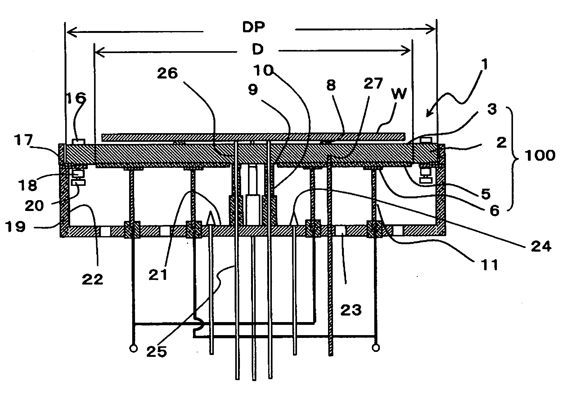
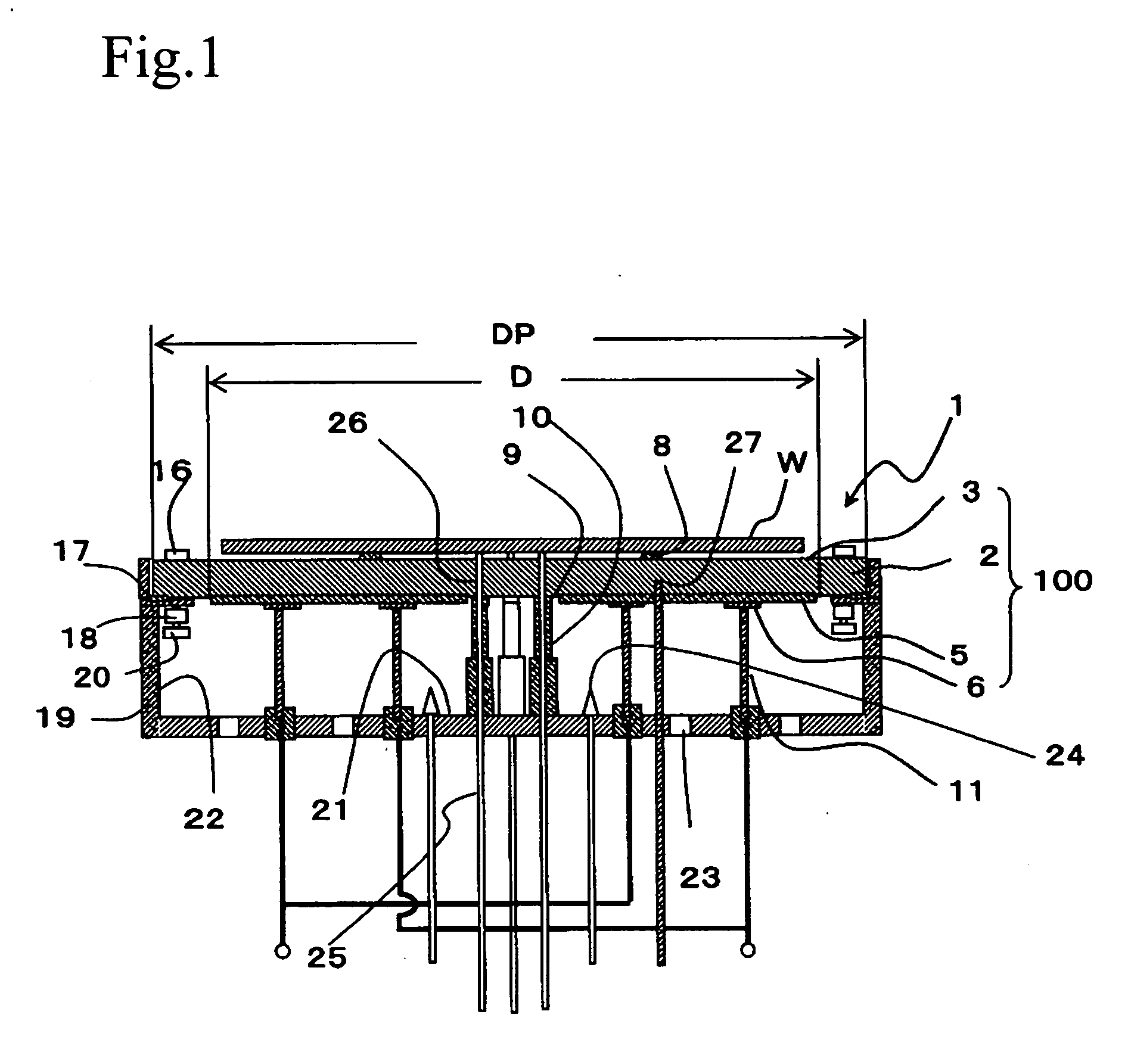
Heater for heating a wafer and method for fabricating the same
a technology for heating and wafers, applied in the direction of ohmic resistance heating, heating arrangements of hot plates, lighting and heating apparatus, etc., can solve the problem of difficult to maintain the uniform heating balance of the wafer surface up to 0 and the in-plane temperature difference of the wafer, and achieve good production yield and mass production. , the effect of preventing resistance variation
- Summary
- Abstract
- Description
- Claims
- Application Information
AI Technical Summary
Benefits of technology
Problems solved by technology
Method used
Image

Examples
example 1
[0281] A silicon carbide sintered compact having thermal conductivity of 80 W / (m·K) was subjected to grinding to thus prepare a plurality of uniform heating plates taking a shape of a disc having a thickness of 4 mm and an outer diameter of 230 mm. In order to bond an insulating layer on one main surface of each uniform heating plate, a glass paste prepared by kneading ethyl cellulose as a binder and terpineol as an organic solvent with glass powder was laid by a screen printing method, heated at 150° C. to dry the organic solvent, defatted for 30 minutes at 550° C., and then subjected to baking at a temperature of 700 to 900° C. again. Thereby, the insulating layer composed of glass and having a thickness of 200 μm was formed. Subsequently, in order to bond a resistance heating element on the insulating layer, 20% by weight Au powder, 10% by weight Pt powder and 70% by weight glass as a conductive material were printed in a shape of a predetermined quantity of resistance heating el...
example 2
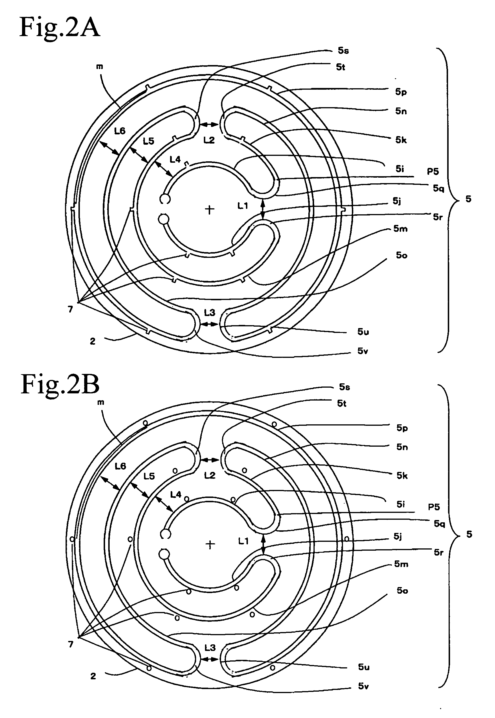
[0291] Samples were prepared in the same method as in Example 1. Further, the positioning mark configured of a protrusion shown in FIG. 6 was formed. Thereby, ceramic heaters forming a channel outside the belt, inside the belt, and in the middle of the belt were prepared. In addition, for the sake of comparison, a ceramic heater where the channels were present inside and outside was prepared.
[0292] Further, the belt of the resistance heating element was formed at a width of 1.5 mm, and then the belt was form with a group of channels by the laser. The channel group was formed on a portion of the belt located outside the plate shaped ceramics body. And, a sample changing an interval between the channel group and the channel group was prepared.
[0293] Further, the interval between the group and the group referred to dividing each resistance heating element zone of resistance heating elements into portions, lessening resistance deviation of each portion of each resistance heating eleme...
example 3
[0298] A silicon carbide sintered compact having thermal conductivity of 80 W / (m·K) was subjected to grinding to thus prepare a plurality of uniform heating plates taking a shape of a disc having a thickness of 4 mm and an outer diameter of 230 mm. In order to bond an insulating layer on one main surface of each uniform heating plate, a glass paste prepared by kneading ethyl cellulose as a binder and terpineol as an organic solvent with glass powder was laid by a screen printing method, heated at 150° C. to dry the organic solvent, defatted for 30 minutes at 550° C., and then subjected to baking at a temperature of 700 to 900° C. again. Thereby, the insulating layer composed of glass and having a thickness of 200 μm was formed. Subsequently, in order to bond a resistance heating element on the insulating layer, 20% by weight of Au powder, 10% by weight of Pt powder and 70% by weight of glass as a conductive material were printed in a shape of a predetermined quantity of pattern, and...
PUM
 Abstract
Description
Claims
Application Information