High performance defrosters for transparent panels
a transparent panel and high-performance technology, applied in the direction of ohmic-resistance heating, heater elements, transportation and packaging, etc., can solve the problems of increasing the overall design and shape complexity, the limited ability of plastics to conduct heat, and the limitations of plastic modules, so as to increase the spacing between high-visibility grid lines, improve the performance of plastic panels or windows, and improve the effect of grid line spacing
- Summary
- Abstract
- Description
- Claims
- Application Information
AI Technical Summary
Benefits of technology
Problems solved by technology
Method used
Image
Examples
example 1
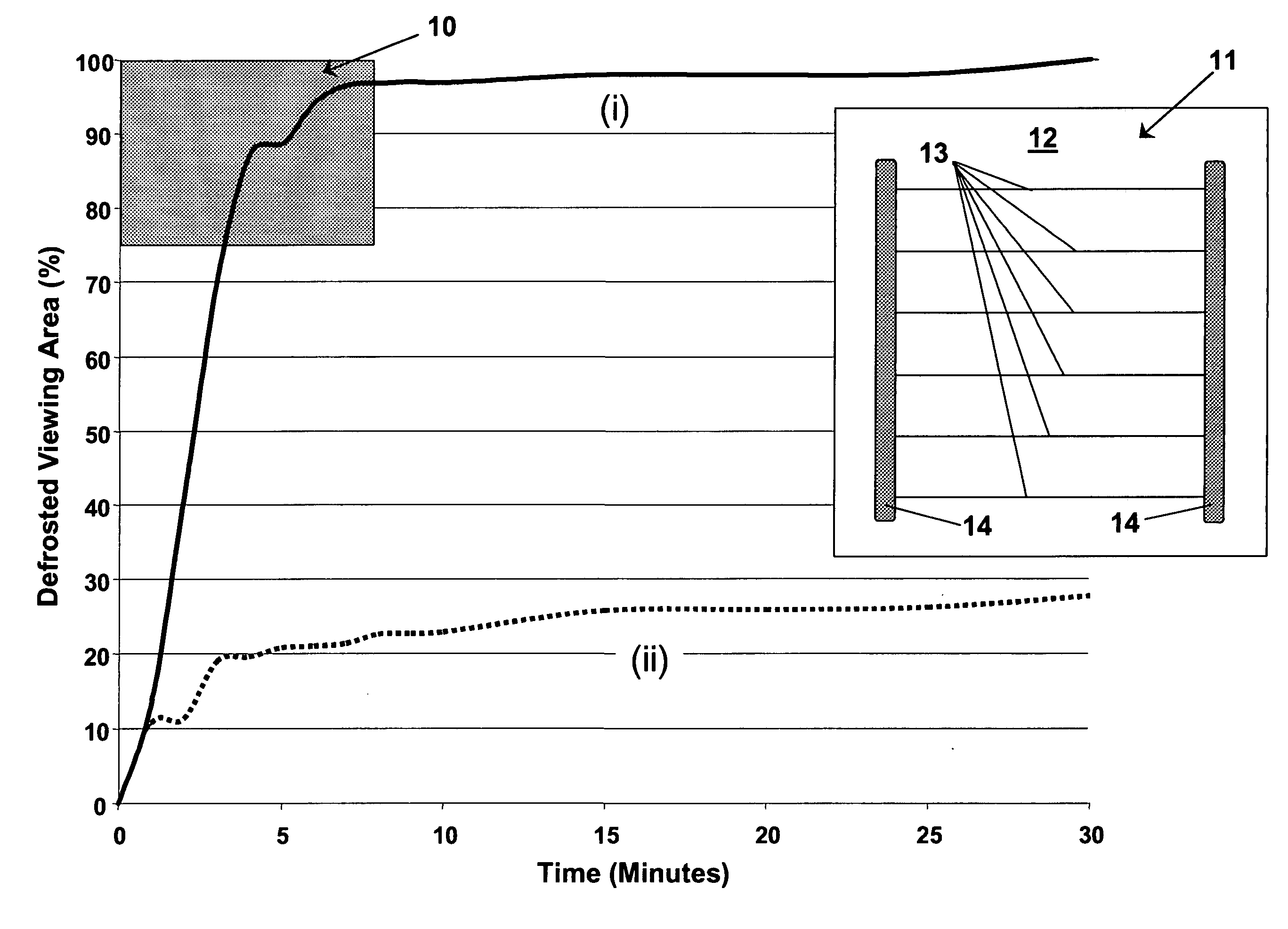
[0063] A heater grid test pattern 18 as shown in FIG. 8 was constructed to evaluate the ability of a various heater grid designs comprising different spacing between the first group of grid lines 20 with width W1 and different numbers of grid lines 35 in the second group with width W2 to defrost a plastic window 16 according to industry standard defrost test protocols and to emulate the defrosting capability of a heater grid on a glass window. A total of 10 different combinations were evaluated in this test pattern. All measurements identifying each combination are provided in Table 3. More specifically, this test pattern evaluated a distance (D1) of 30 mm (a-c), 40 mm (d-f), and 50 mm (g-j) between the first group of grid lines 20, as well as a total of 1 grid line (a), 2 grid lines (b-e, g), 3 grid lines (f and h), 4 grid lines (i), and 5 grid lines (j) within the second group of grid lines 35 between adjacent ones of the grid lines 20 of the first group. The distance between the ...
example 2
A Heater Grid for a Plastic Automotive Backlight
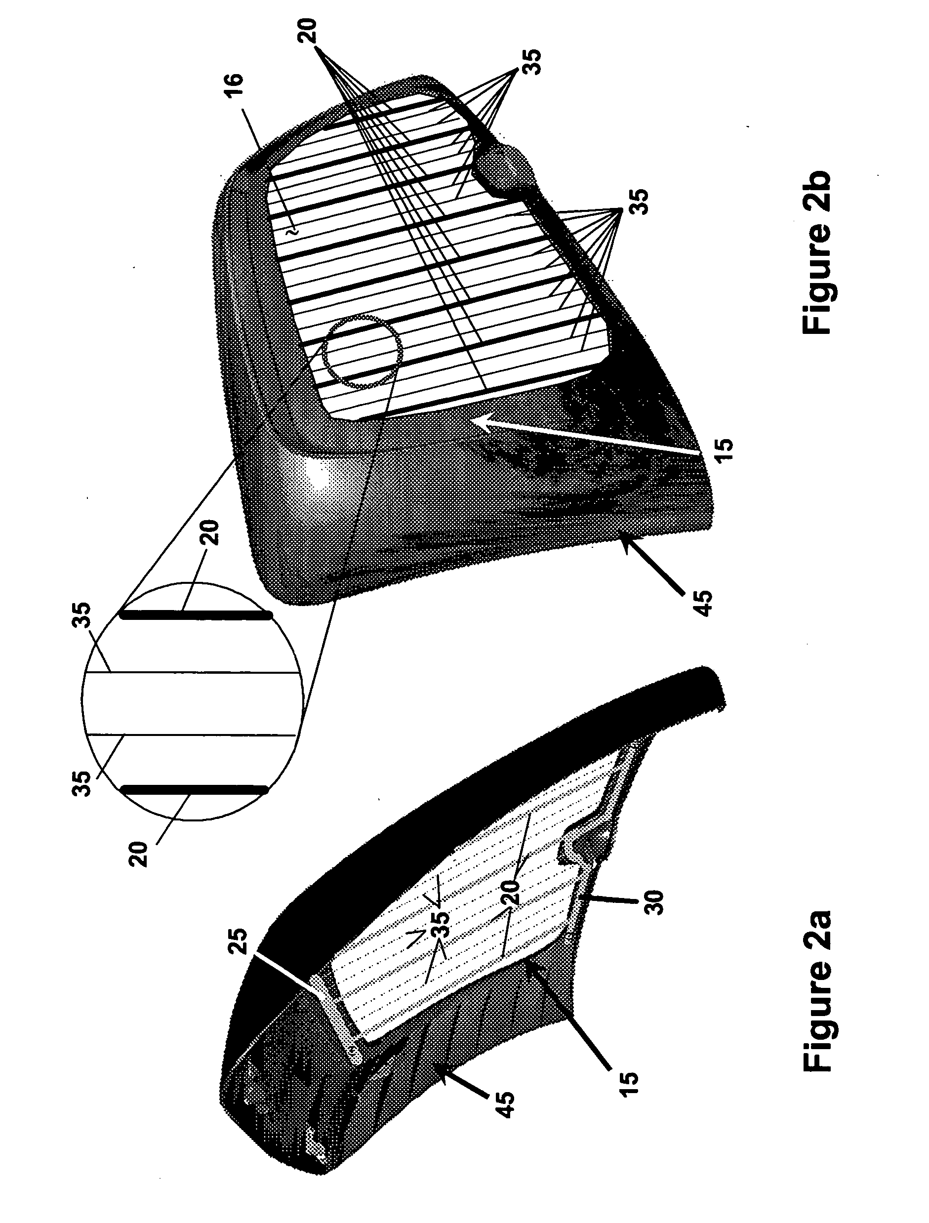
[0069] A heater grid comprising eight first groups and 8 second groups of grid lines was designed for an automotive backlight as shown in FIG. 3. Each grid line in the first group and second group of grid lines exhibited a width (W1) of 1.25 mm and a width (W2) of 0.225 mm, respectively. Each second group of grid lines was comprised of three grid lines. The length of the gridlines in the first group (L1) and the second group (L2) of grid lines were both about 616 mm. All of the grid lines were relatively parallel to each other with the distance (D1) between the grid lines in the first group being about 50 mm and the distance (D2) between the grid lines in the second group being about 12.5 mm. The resistance of the grid lines in the first group (R1) and in the second group (R2) was 12.5 ohms and 69.5 ohms, respectively. The ratio of (W2 / W1), (D1 / D2), (R2 / R1), and (A2 / A1) was determined to be 0.18, 4.0, 5.56, and 0.956, respectively.
[0...
PUM
 Abstract
Description
Claims
Application Information
 - R&D
- Intellectual Property
- Life Sciences
- Materials
- Tech Scout
- Unparalleled Data Quality
- Higher Quality Content
- 60% Fewer Hallucinations
Browse by: Latest US Patents, China's latest patents, Technical Efficacy Thesaurus, Application Domain, Technology Topic, Popular Technical Reports.
© 2025 PatSnap. All rights reserved.Legal|Privacy policy|Modern Slavery Act Transparency Statement|Sitemap|About US| Contact US: help@patsnap.com


