Light source module and vehicle front lamp

a technology for light source modules and vehicle front lamps, which is applied in the direction of fixed installations, lighting and heating apparatus, and light source modules. it is difficult to efficiently radiate the light generated by the semiconductor light-emitting element to the outside of the light source modul

Inactive Publication Date: 2005-11-17
KOITO MFG CO LTD
View PDF4 Cites 79 Cited by
  • Summary
  • Abstract
  • Description
  • Claims
  • Application Information

AI Technical Summary

Benefits of technology

[0007] Therefore, an object of the present invention is to provide a light source module and a vehicle front lamp to solve the aforementioned problem.

Problems solved by technology

Consequently, there is a possibility that part of the light generated by the semiconductor light-emitting element will not be applied onto the fluorescent substance in the binder.
For this reason, it might be impossible to radiate the light generated by the semiconductor light-emitting element to the outside of the light source module efficiently.

Method used


Image

  • Light source module and vehicle front lamp
  • Light source module and vehicle front lamp
  • Light source module and vehicle front lamp

Examples


examples concerned

[0107] Examples concerned with the nano-particles and the binder will be described below.

[0108] Evaluation was made on the case where the nano-particles and the binder were applied to a semiconductor light-emitting element for emitting blue light and a semiconductor light-emitting element for emitting ultraviolet light, respectively.

[0109] The refractive index of the binder composition after addition of the nano-particles into 10% by volume of the binder was calculated based on proportion. The reflectance of the binder composition was calculated in the condition that light was incident onto the binder composition perpendicularly from the light-emitting element having a refractive index of 1.77.

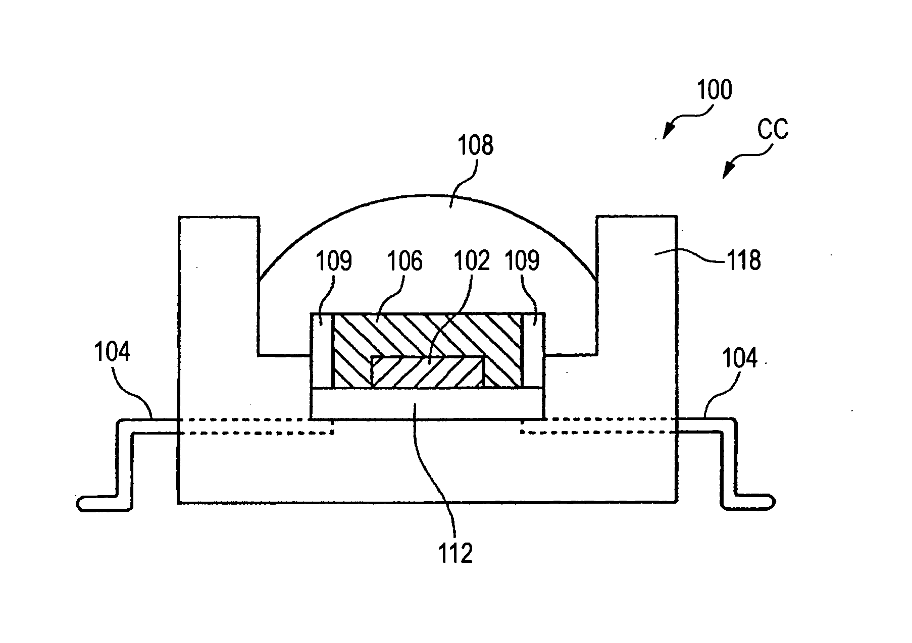
[0110] The light emitted from the light-emitting element incidents to the binder 606, then wavelength of the light is converted at the fluorescent substance 604 and white light is obtained at outside of the LED module 100. When obtaining the light from the light-emitting element to the outsi...

examples 1 and 2

[0113] Examples 1 and 2 and Comparative Examples 1 to 3 were evaluated on the assumption that the sample was applied to a light-emitting element for emitting blue light (460 nm).

[Example 1]Nano-Particles: aluminum oxide C (madeby NIPPON AEROSIL CO., LTD.)particle size 13 nm, refractive index 1.77,forbidden band width energy 8.3 eVBinder: phenylsilicone compound (made by GELEST, INC.)(thermally bridged substance of the following mixture)Vinyl-terminal diphenylsiloxane-dimethylsiloxane94.92wt %copolymer:Curing catalyst: SIP6831.2:0.08wt %Crosslinker: HMS-301:5.00wt %Refractive index1.53[Example 2]Nano-Particles: titanium oxide P25(made by NIPPON AEROSIL CO., LTD.)particle size 21 nm, refractive index 2.50,forbidden band width energy 3.2 eVBinder: phenylsilicone compound (made by GELEST, INC.)(thermally bridged substance of the following mixture)Vinyl-terminal diphenylsiloxane-dimethylsiloxane94.92wt %copolymer:Curing catalyst: SIP6831.2:0.08wt %Crosslinker: HMS-301:5.00wt %Refractive ...


PUM

PropertyMeasurementUnit
diameteraaaaaaaaaa
forbidden bandwidth energyaaaaaaaaaa
refractive indexaaaaaaaaaa

Abstract

A light source module for generating light, including a semiconductor light-emitting element, nano-particles having a diameter smaller than half the wavelength of light generated by the light source module, a fluorescent substance for generating visible light in accordance with light generated by the semiconductor light-emitting element, and a binder formed stratiformly for covering a light-emitting surface of the semiconductor light-emitting element to hold the nano-particles and the fluorescent substance, wherein the refractive index of the nano-particles is higher than the refractive index of the binder.

Description

[0001] The present invention claims foreign priority to Japanese patent application no. P. 2004-093172, filed on Mar. 26, 2004 and no. P. 2005-052893 filed on Feb. 28, 2005, the contents of which are incorporated herein by reference. BACKGROUND OF THE PRESENT INVENTION [0002] 1. Field of the Present Invention [0003] The present invention relates to a light source module and a vehicle front lamp. [0004] 2. Description of the Related Art [0005] A light source module using a semiconductor light-emitting element and a fluorescent substance for generating white light has been heretofore known (e.g. see Ohm MOOK Optical Series No. 1 “Optical Devices” Ohmsha, Ltd., Nov. 25, 2001). The fluorescent substance generates visible light in accordance with light generated by the semiconductor light-emitting element. The fluorescent substance is held in a transparent binder. For example, the fluorescent substance is formed stratiformly on a light-emitting surface of the semiconductor light-emitting...

Claims


Application Information

Patent Timeline
Patent Type & Authority Applications(United States)
IPC IPC(8): F21S8/10B82B1/00C09J127/12C09J183/00C09K11/02F21K2/00F21S8/12F21W101/10F21YF21Y101/02H01L29/06H05B33/20
CPCC09K11/02H01L33/501H05B33/20H01L2933/0091H01L33/56C09K11/08H01L2224/73204E04H12/08F21S8/085
Inventor TSUTSUMI, YASUAKIDAICHO, HISAYOSHITAKEDA, HITOSHIHAYAMA, HIDEKAZUYAMAGUCHI, HIROKAZU
Owner KOITO MFG CO LTD
Why Eureka
Try Eureka