Non-contact heater and method for non-contact heating of a substrate for material deposition

a non-contact heating and substrate technology, applied in the field of non-contact heating of objects, can solve the problems of degrading its properties, unwanted obstacles in the deposition of high-quality films of multi-component materials, and relatively expensive production

Active Publication Date: 2005-11-17
NEOCERA
View PDF6 Cites 3 Cited by
  • Summary
  • Abstract
  • Description
  • Claims
  • Application Information

AI Technical Summary

Benefits of technology

[0011] It is an object of the present invention to provide a non-contact heater and a technique for the stable and uniform non-contact heating of a substrate surface to a temperature optimal for multi-component material deposition.

Problems solved by technology

This causes unwanted obstacles in the deposition of high quality films of multi-component materials.
The re-evaporation of the material components from the walls will change the composition of the film growing on the substrate and, as a result, may degrade its properties.
Disadvantageously, the laser radiation of sufficient power (˜0.5 kW for the substrates of reasonably large area ˜10 cm2) is relatively expensive to produce, and it is difficult to attain a uniform and stable temperature Ts over the substrate area in the open heater arrangement.
The heater arrangements using lamps, in addition to high cost, require the lamps to be protected against the unwanted deposit of material.
To lower the material deposited on the lamp surface, the lamps are usually distanced from the substrate, which requires radiation delivery optics, including focusing elements, mirrors, etc., resulting in further degradation of the uniformity and stability of the substrate temperature.

Method used


Image

  • Non-contact heater and method for non-contact heating of a substrate for material deposition
  • Non-contact heater and method for non-contact heating of a substrate for material deposition
  • Non-contact heater and method for non-contact heating of a substrate for material deposition

Examples


Embodiment Construction

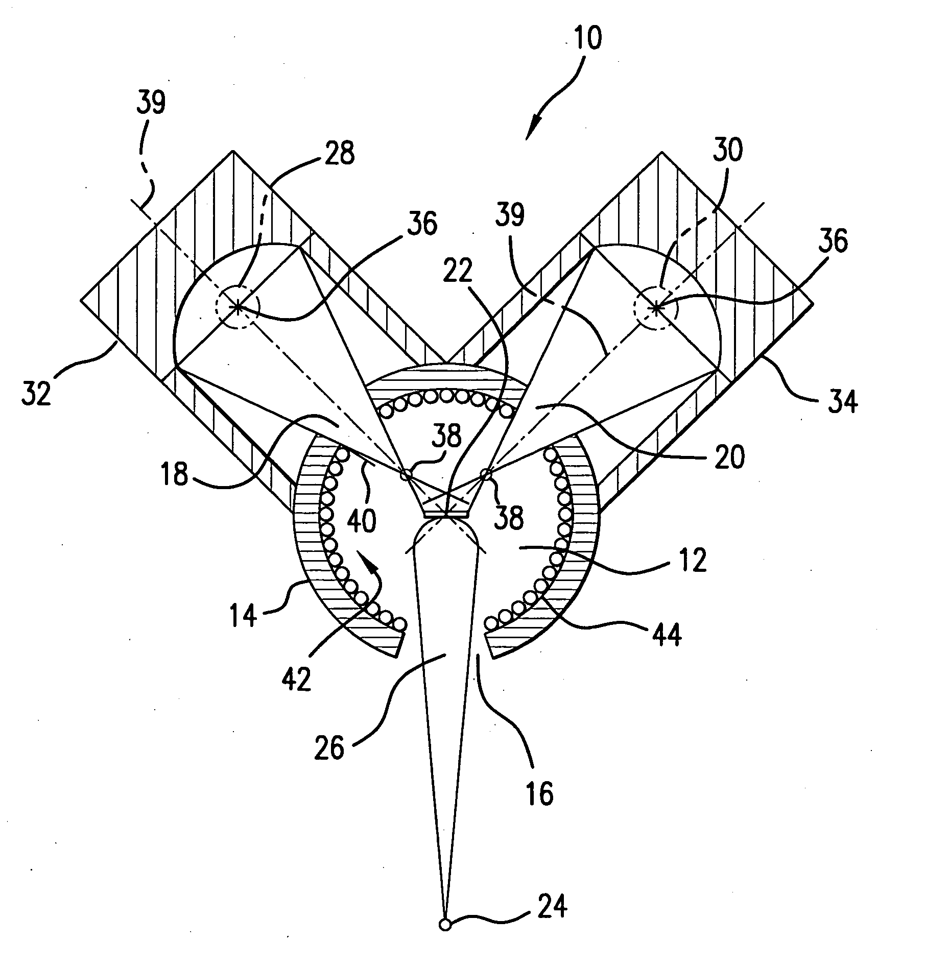
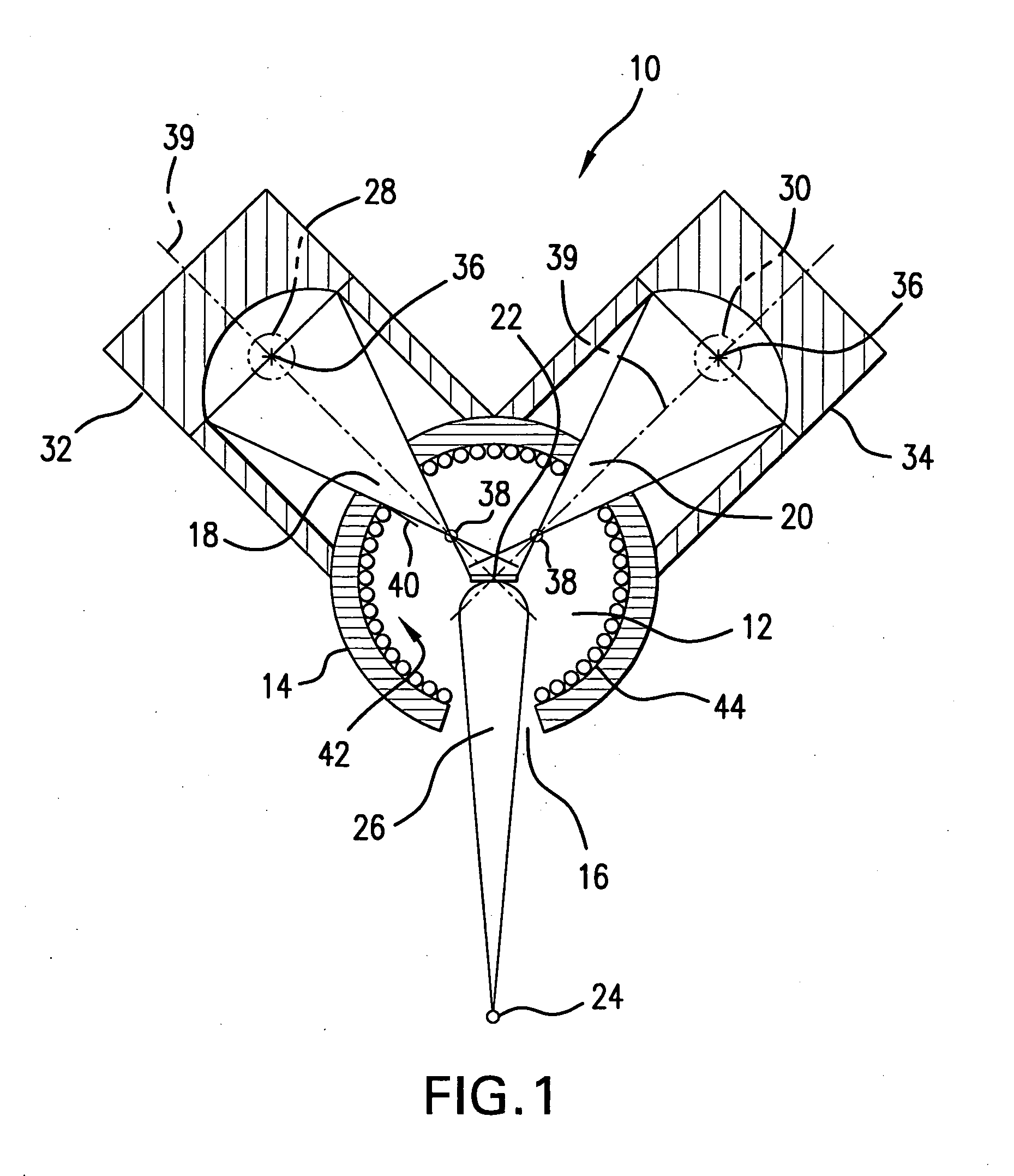
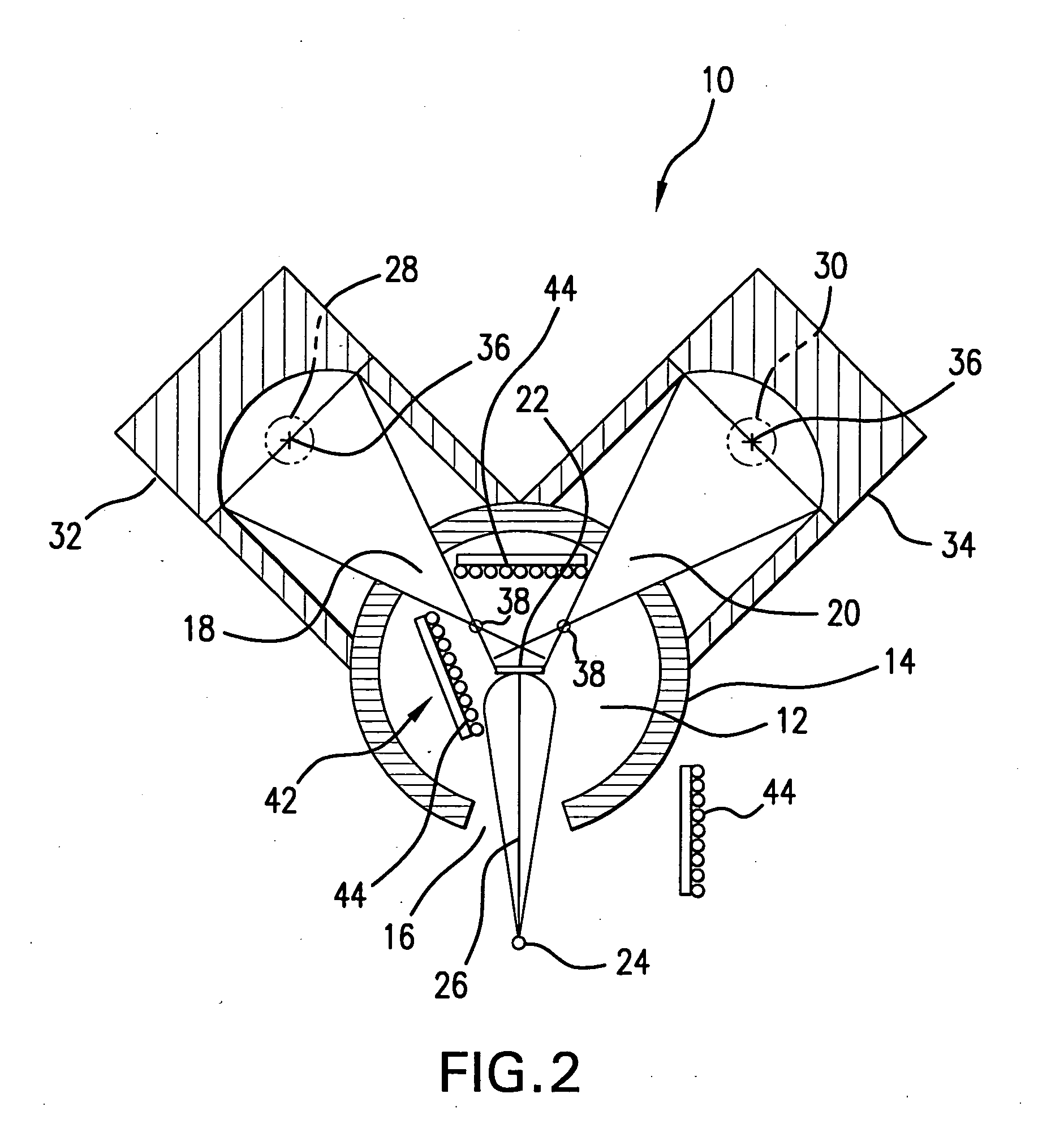
[0044] The principles of the present inventive concept are applicable to the non-contact heating of any object, however, for purposes of a better understanding of the present invention, and as one of the examples of the particular application of the subject non-contact heating technique, the following description is directed primarily to the non-contact heating of a substrate for material deposition. As such, referring to FIGS. 1 and 2, a non-contact heater 10 includes a housing which has a deposition cavity 12 defmed by a housing wall (or a cavity wall) 14, in which a deposition opening 16 and a pair of radiation paths 18 and 20 are formed. An object to be heated; e.g., a substrate 22, is mounted internal the deposition cavity 12 at a predetermined position therein. A deposition source 24 is mounted remotely from the deposition cavity 12 to generate a deposition flux 26, which enters the deposition cavity 12 through the deposition opening 16 for coating the substrate 22 to form cry...


PUM

PropertyMeasurementUnit
areaaaaaaaaaaa
diameteraaaaaaaaaa
diameteraaaaaaaaaa

Abstract

A heater for the non-contact heating of an object, such as a substrate for material deposition, includes a housing defining a deposition cavity and a source of radiation outside the deposition cavity. A reflector is optically coupled to the source of radiation to collect the radiation and to focus it on the radiation path. The reflector may have different shapes. If, for example, the reflector is an ellipsoidal reflector, the source of radiation then is mounted in a first focus, the substrate is located in the other focus, and the radiation path is positioned on the main focal axis of the ellipsoidal reflector. The radiation from the source of radiation is delivered to the substrate inside the deposition cavity through a radiation path(s) formed in the housing wall to heat the substrate to the temperature Ts, so that T1<Ts<T2, where T1 is the temperature of the housing wall, while T2 is the effective temperature of the source of radiation.

Description

FIELD OF THE INVENTION [0001] The present invention relates to the non-contact heating of an object. The present invention is directed particularly to the heating of a substrate for thin film deposition in the absence of convective heating. [0002] More particularly, the present invention relates to a system and method for the non-contact heating of a substrate positioned in a deposition cavity by optical radiation emanating from a radiation source located outside the walls of the deposition cavity in order to reach an optimal substrate temperature for material deposition. BACKGROUND OF THE INVENTION [0003] Non-contact (irradiative) heating is needed in the deposition of thin films onto a moving substrate in the absence of convective (gas) heating. It is customary to employ a cavity-type heater where a substrate is disposed in the cavity while the walls of the cavity-type heater are heated to a predetermined temperature T1. In an ideal cavity, due to radiation exchange, the substrate...

Claims


Application Information

Patent Timeline
Patent Type & Authority Applications(United States)
IPC IPC(8): H01L21/00H01L33/00H05B3/00
CPCH05B3/0047H01L21/67115
Inventor STRIKOVSKI, MIKHAILHARSHAVARDHAN, KOLAGANI SOLOMON
Owner NEOCERA
Why Eureka
Try Eureka