NMR magnet device for solution analysis and NMR apparatus
- Summary
- Abstract
- Description
- Claims
- Application Information
AI Technical Summary
Benefits of technology
Problems solved by technology
Method used
Image
Examples
second embodiment
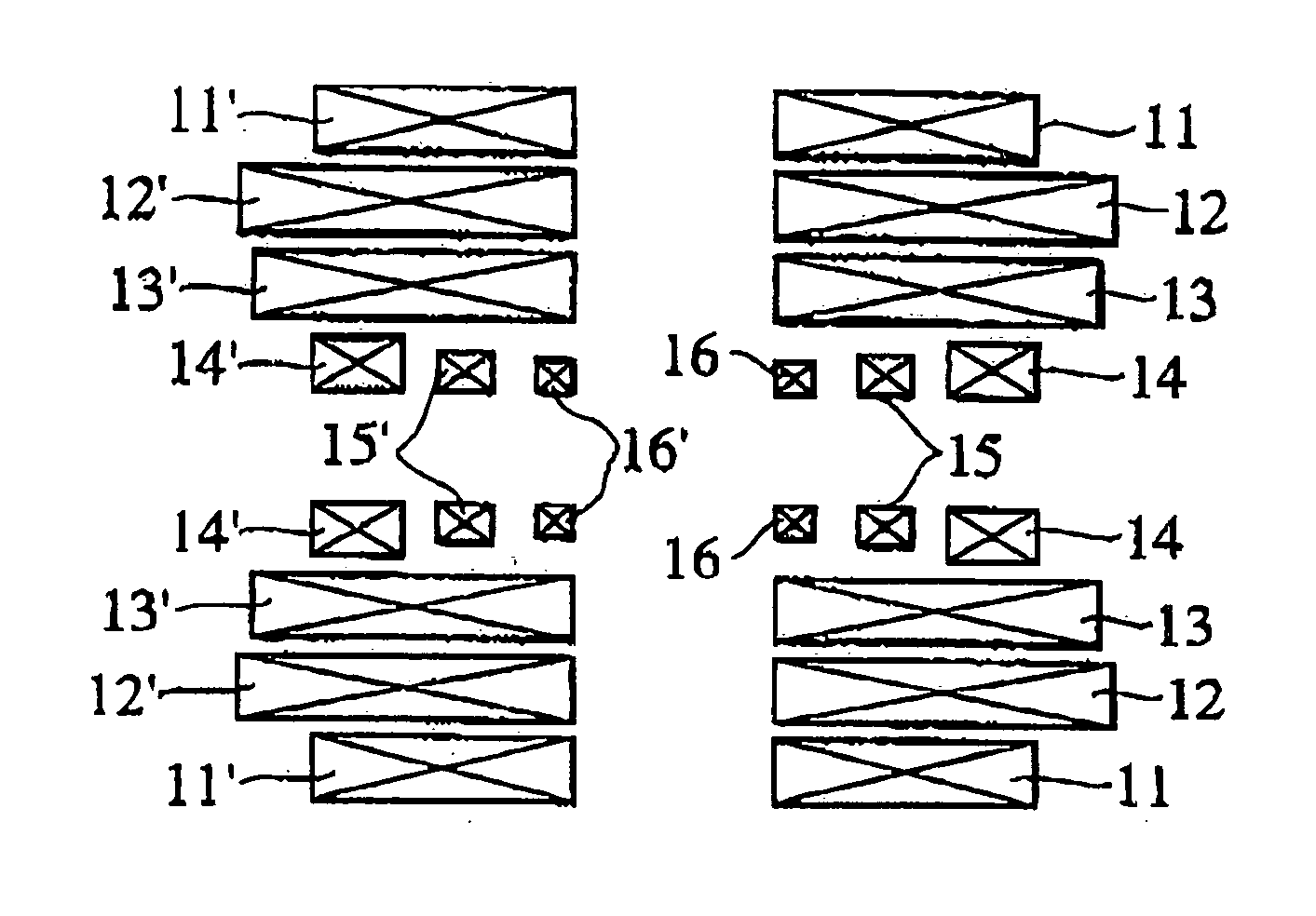
[0055] An arrangement of superconducting coils, according to the present invention, is shown in FIG. 2. Each of the pairs of (left and right) superconducting coils 11 to 16 and 11′ to 16′ (ex., the pair of 11 and 11′) is arranged so as to be substantially concentric with respect to a central axis extending along the horizontal direction. The left and right multilayer superconducting coils are arranged substantially symmetrically with respect to a center face extending along the vertical direction of the magnet device, and a certain distance is maintained between the centerline and each of the multilayer superconducting coils. The superconducting coils 14, 15, and 16 form the innermost layer, wherein the superconducting coils 15 and 15′ are energized in such a manner that the magnetic field generated thereby is in a direction reverse to that generated at the central part. Thus, a magnetic field of ppb-order uniformity is formed at the center portion of the split type magnet device of...
third embodiment
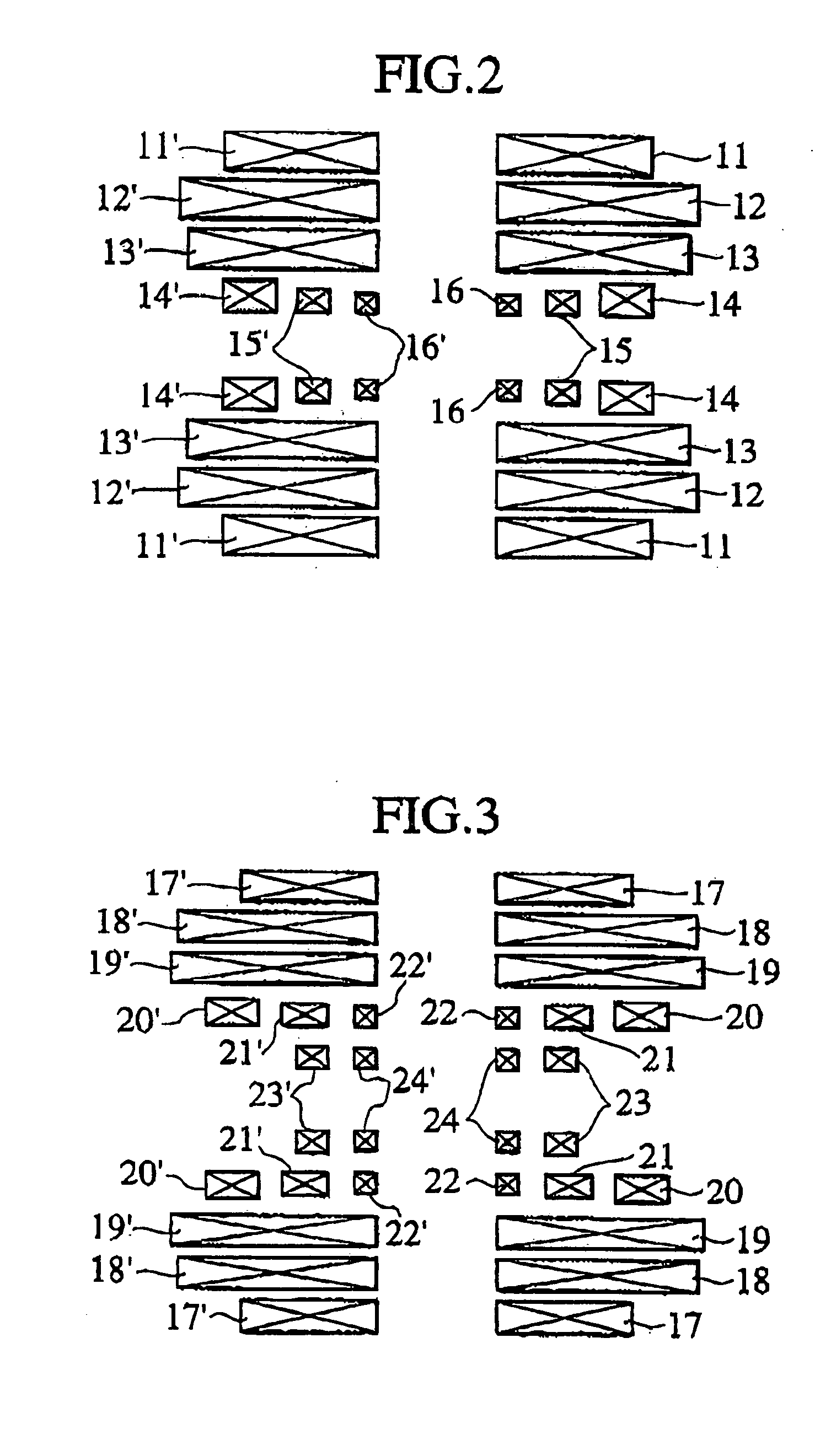
[0056] An arrangement of superconducting coils, according to the present invention, is shown in FIG. 3. Each of the pairs of (left and right) superconducting coils 17 to 24 and 17′ to 24′ (ex., the pair of 17 and 17′) is arranged substantially concentric with respect to a central axis extending along the horizontal direction. The left and right multilayer superconducting coils are arranged substantially symmetrically with respect to a center face extending along the vertical direction of the magnet device, and a certain distance is maintained between the center face and each of the multilayer superconducting coils. Among the layers formed by the pairs of (left and right) superconducting coils, the innermost layers are formed of the superconducting coils 23, 23′, 24 and 24′, and layers disposed radially outward from the innermost layers are formed of the superconducting coils 20, 20′, 21, 21′, 22 and 22′. The pair of superconducting coils 22 and 22′ and the pair of superconducting co...
fourth embodiment
[0057] The NMR apparatus should desirably have a small leakage magnetic field; and, therefore, a fourth embodiment, which will described hereinafter, includes a shielding of the leakage magnetic field.
[0058] An arrangement of superconducting coils according to the fourth embodiment of the present invention is shown in FIG. 4. Superconducting coils 26 to 30 and 26′ to 30′ generate a uniform magnetic field at the center portion of the magnet device. In the present embodiment, the superconducting coil 30 and 30′ are energized to generate a magnetic field which is in a direction reverse to that generated by the other coils, so that a magnetic field of ppb-order uniformity is generated. Superconducting shielding coils 25 and 25′ are active shielding coils used for suppressing the leakage of the magnetic field.
PUM
 Abstract
Description
Claims
Application Information
 - R&D
- Intellectual Property
- Life Sciences
- Materials
- Tech Scout
- Unparalleled Data Quality
- Higher Quality Content
- 60% Fewer Hallucinations
Browse by: Latest US Patents, China's latest patents, Technical Efficacy Thesaurus, Application Domain, Technology Topic, Popular Technical Reports.
© 2025 PatSnap. All rights reserved.Legal|Privacy policy|Modern Slavery Act Transparency Statement|Sitemap|About US| Contact US: help@patsnap.com


