Inverter device and inverter module

a technology of inverter device and inverter module, which is applied in the direction of motor/generator/converter stopper, dynamo-electric converter control, dc-ac conversion without reversal, etc., can solve the problems of increased size of the entire device, electric shock to the person, and inability to detect the welding of the switch, etc., to achieve the effect of reducing the size and reducing the installation spa

Inactive Publication Date: 2005-11-17
SANYO ELECTRIC CO LTD
View PDF5 Cites 17 Cited by
  • Summary
  • Abstract
  • Description
  • Claims
  • Application Information

AI Technical Summary

Benefits of technology

[0022] According to this invention, in an inverter module comprising a switching element group provided in a mold package to convert a DC voltage into a three-phase pseudo AC voltage by switching, a diode provided between a DC power source and the switching element group and directed forward to the switching element group side is integrally molded into the mold package, whereby a significant size reduction can be achieved as compared with the case in which the diode to prevent damages and electric shocks due to reverse connection of the DC power source is provided in an external substrate, and the installation space can be reduced. Moreover, the molding allows heat release of the diode and also allows an insulation distance to be secured at the same time, which makes it possible to configure a high-performance inverter module.
[0023] Furthermore, there is provided a pin to connect, to a forward side of the diode, the capacitor charged from the DC power source via the charging device, so that the diode and capacitor can be connected without trouble.

Problems solved by technology

However, the high-capacity capacitor 406 is placed in the inverter device 408 as described above, and a measured voltage is not immediately reduced due to a discharge voltage of the capacitor 406, so that it has not been possible to detect the welding of the switch 402 in early stages.
Further, there is a disadvantage that when a person touches a terminal on the battery 401 side, the person gets an electric shock because of the charged capacitor 406.
However, the addition of the diode leads to an increase in size of the entire device.
On the other hand, especially in the air conditioner for the electric automobile, because the inverter device is installed on a vehicle to drive the electrically driven compressor, it has to be placed in a small engine room having limited installation space, so that the size increase is not allowed, and a further size reduction has been needed.

Method used


Image

  • Inverter device and inverter module
  • Inverter device and inverter module
  • Inverter device and inverter module

Examples


embodiment 1

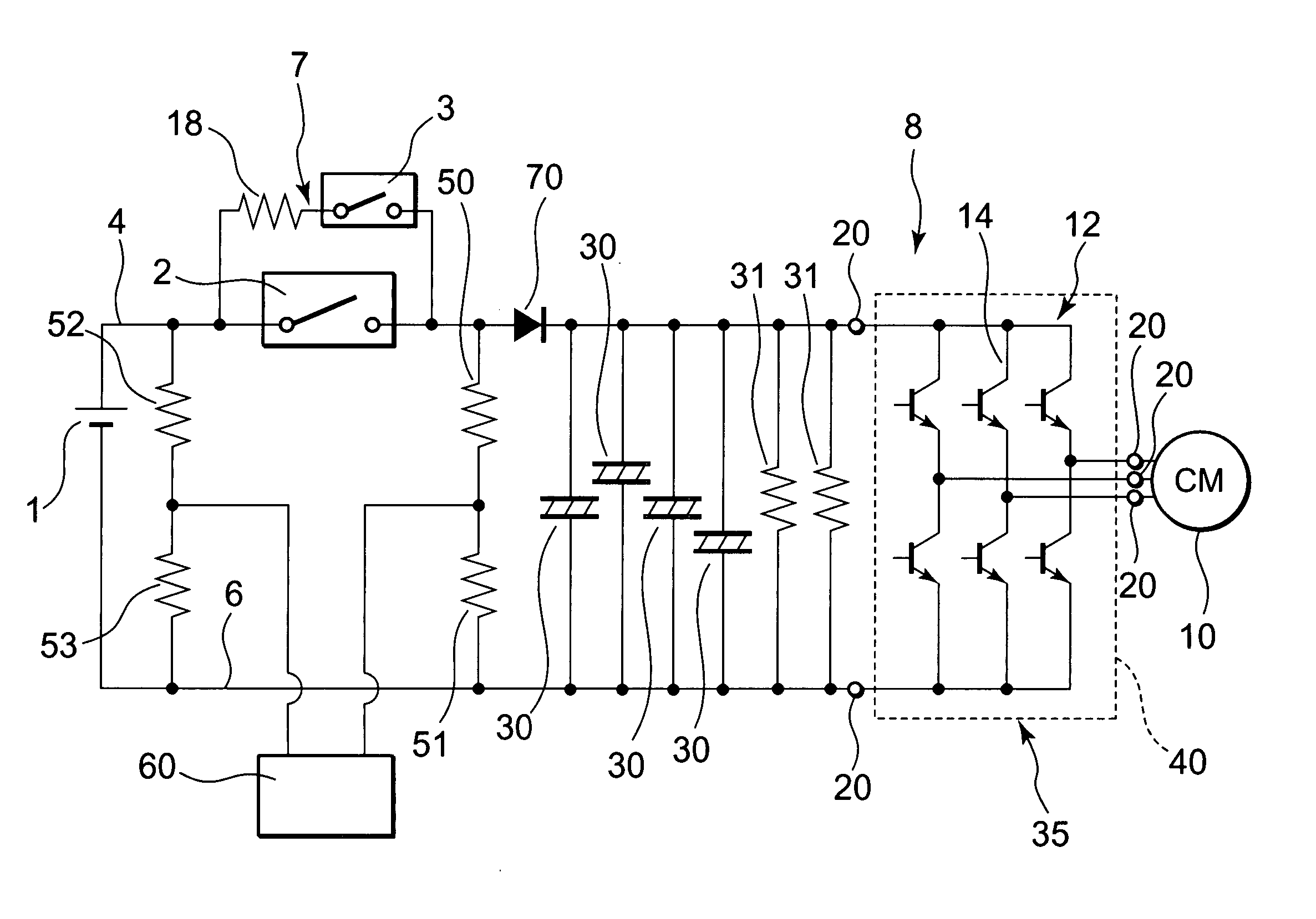
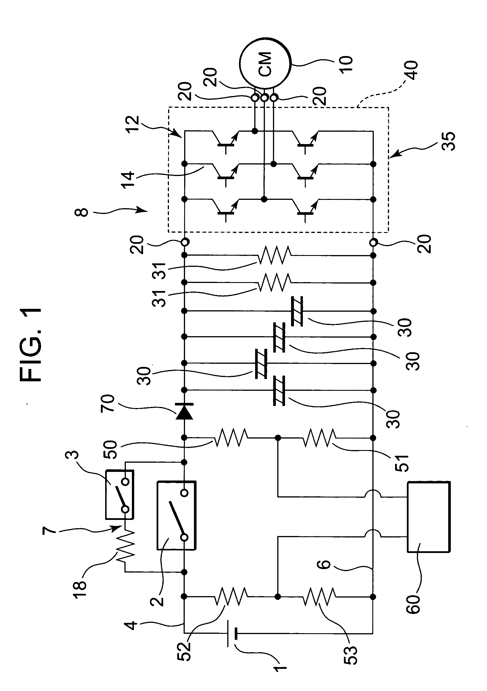
[0032]FIG. 1 is an electric circuit diagram of one embodiment of an air conditioner for an electric automobile comprising an inverter device 8 of the present invention.

[0033] In FIG. 1, 1 is a main battery as a DC power source of the electric automobile, and this provides power to an electrically driven compressor 10 of the air conditioner via the inverter device 8 of the present invention. A DC voltage is output from the battery 1, but a voltage converted into a three-phase pseudo AC is supplied to (a motor of) the electrically driven compressor 10 by an inverter module 35 (an inverter in the present invention) of the inverter device 8 described later.

[0034] The above-mentioned inverter device 8 comprises a switch 2 as a switching device, a charging circuit 7 as a charging device, four capacitors 30 . . . , discharging resistors 31, 31, the inverter module 35, and the like.

[0035] The above-mentioned inverter module 35 comprises a switching element group 12 provided in a mold pac...

embodiment 2

[0055] Next, another embodiment of the invention will be described using FIG. 4 and FIG. 5.

[0056]FIG. 4 shows an electric circuit diagram of the air conditioner for the electric automobile of the invention in this case, and FIG. 5 shows a perspective view of an inverter module 135 in this embodiment.

[0057] In FIG. 4, 101 is a main battery as the DC power source of the electric automobile, and this provides a DC power source to an electrically driven compressor 110 of the air conditioner via an inverter device 108 comprising a switch 102, a charging circuit 107 as a charging device, a capacitor 130, a discharging resistor 131, the inverter module 135 of the present invention, and the like. A DC voltage is output from the battery 101, but a voltage converted into a three-phase pseudo AC is supplied to the electrically driven compressor 110 by the inverter module 135 described later.

[0058] The above-described inverter module 135 comprises a switching element group 112 provided in a ...

embodiment 3

[0076] Next, another embodiment of the inverter module will be described using FIG. 6. FIG. 6 shows an electric circuit diagram of one embodiment of the air conditioner for the electric automobile comprising an inverter module 235 in this case. It is to be noted that in FIG. 6, those assigned with the same sings as in FIG. 4 and FIG. 5 have the same or similar effects.

[0077] In FIG. 6, 235 is the inverter module of the present embodiment, and a voltage converted into a three-phase pseudo AC by the inverter module 235 is supplied to the electrically driven compressor 110.

[0078] This inverter module 235 comprises the switching element group 112 provided in the mold package 140 to convert the voltage into the three-phase pseudo AC voltage by switching, as in the embodiments described above. This switching element group 112 comprises the switching element 114 and an unshown diode to absorb a switching surge, and is connected between the positive line 104 (about DC+350 V) and the negat...


PUM


Abstract

An object is to provide an inverter device capable of detecting the welding of a switching device in early stages, and in summary, the inverter device is equipped with a parallel circuit of a charging circuit and a switch connected between a battery and an inverter module, and comprises a capacitor charged from the battery via the charging circuit; a resistor to discharge the capacitor; a serial circuit including resistors to detect a voltage after the switch; and a diode connected between a connection point of the serial circuit including the resistors on a positive line and a connection point of the capacitor, and directed forward to the capacitor side.

Description

BACKGROUND OF THE INVENTION [0001] 1. Field of the Invention [0002] The present invention relates to an inverter device comprising a parallel circuit of a charging device and a switching device connected between a DC power source and an inverter, and to an inverter module comprising a switching element group provided in a mold package to convert a DC voltage into a three-phase pseudo AC voltage by switching. [0003] 2. Description of the Related Art [0004] Recently, an air conditioner equipped with an electrically driven compressor driven by a battery power source has been developed as an air conditioner for an electric automobile. This air conditioner comprises, as shown in FIG. 7, a battery (DC power source) 401, an inverter device 408 and an electrically driven compressor 410. [0005] The inverter device 408 comprises a switch 402 as a switching device connected in serial to the battery 401; a charging device 411 connected in parallel to this switch 402 and including a resistor 404...

Claims


Application Information

Patent Timeline
Patent Type & Authority Applications(United States)
IPC IPC(8): H02J7/34H02M7/48H02P6/00
CPCH02J7/345H02M7/48B60L3/003B60L3/0069B60L11/1803Y02T10/7005B60L2240/34B60L2250/10B60L2270/20B60L2240/527H01H2047/003B60L15/007B60L50/51Y02T10/64Y02T10/70
Inventor NOJIMA, KENJISASAKI, SHIGEHARU
Owner SANYO ELECTRIC CO LTD
Why Eureka
Try Eureka