System and method for quality testing of superconducting tape

a superconducting tape and quality testing technology, applied in the field of superconductors, can solve the problems of power dissipation, loss, and undesirable electrical resistance in some applications, and achieve the effects of improving the quality of superconducting tap

Inactive Publication Date: 2005-11-17
METAL OXIDE TECH
View PDF8 Cites 10 Cited by
  • Summary
  • Abstract
  • Description
  • Claims
  • Application Information

AI Technical Summary

Problems solved by technology

Electrical resistance, in some applications, is very undesirable.
For example, in electrical power transmission, electrical resistance causes power dissipation, i.e. loss.
Thus, wires carrying large currents dissipate large amounts of energy.
Moreover, the longer the wire used in either larger transformers, bigger motors or larger transmission distances, the more dissipation, since the resistance in a wire is proportional to its length.
Thus, as wire lengths increase more energy is lost in the wires, even with relatively small currents.
Consequently, electric power plants produce more energy than that which is used by consumers, since a portion of the energy is lost due to wire resistance.
Thus, there is insufficient thermal energy to scatter the pairs, as reversing the direction of travel of one electron in the pair requires the destruction of the pair and many other pairs due to the complex interdependence.
Consequently, the pairs carry current unimpeded.
A problem with YBCO superconductors specifically, and the oxide superconductors in general, is that they are hard to manufacture because of their oxide properties, and are challenging to produce in superconductor form because of their complex atomic structures.
The smallest defect in the structure, e.g. a disordering of atomic structure or a change in chemical composition, can ruin or significantly degrade their superconducting properties.
Defects may arise from many sources, e.g. impurities, wrong material concentration, wrong material phase, wrong processing temperature, poor atomic structure, and improper delivery of materials to the substrate, among others.
The second way has a practical limitation of about 5 feet.
Heating on one side of the chamber, with a cool down on the other side of the chamber may also induce thermal cracks into the YBCO layer and other layers formed on the metal substrate.
The smaller pieces of tape produced by the second method may be spliced together to form a long length tape, but while the pieces may be superconducting, splice technology is not yet at the point of yielding high quality high temperature superconductor splices.
Consequently, current arrangements for forming superconductors cannot form a long, continuous tape of superconductor material.

Method used


Image

  • System and method for quality testing of superconducting tape
  • System and method for quality testing of superconducting tape
  • System and method for quality testing of superconducting tape

Examples


Embodiment Construction

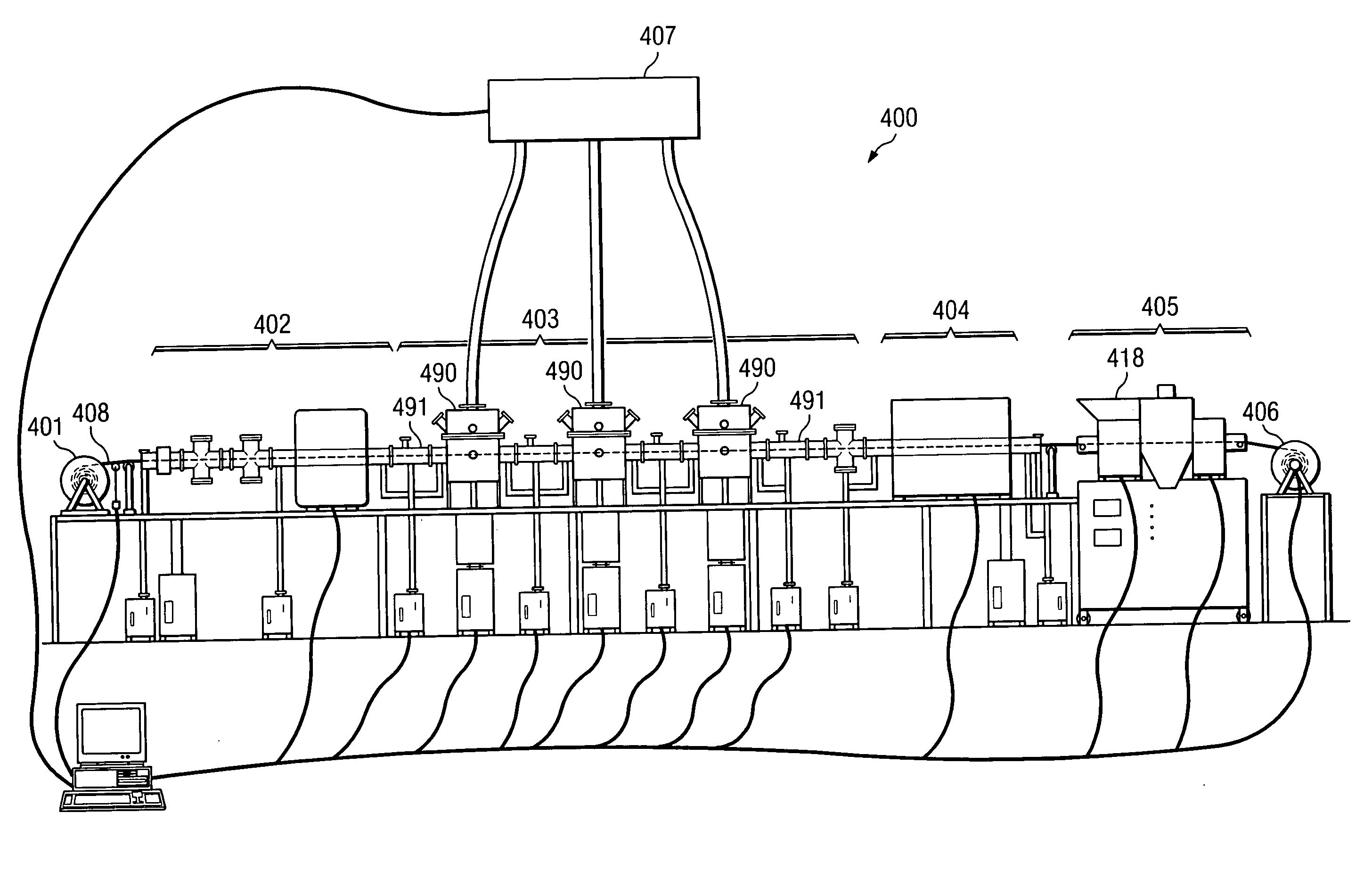
[0026]FIG. 4 is a schematic diagram of an embodiment of exemplary system 400 that produces a continuous tape of high temperature super-conducting (HTS) material. System 400 includes several stages that operate together to deposit superconductor material onto a metallic substrate, such that the HTS material is atomically ordered with large, well-oriented grains and principally low angle grain boundaries. The atomic ordering allows for high current densities, e.g. Jc greater than or equal to 100,000 amps per cm2.

[0027] System 400 uses pay-out reel 401 to dispense tape 408, which is a ribbon of substrate at this point in the process, at a constant rate. The system then uses initialization stage 402 to pre-heat and / or pre-treat tape 408 before growing the superconductor layer and any buffer layers) thereon. Pre-heating may be desirable to lessen thermal shock of the substrate. Pre-treating may also be desirable to reduce contaminants from the substrate before growing the superconductor...


PUM

PropertyMeasurementUnit
Tcaaaaaaaaaa
Tcaaaaaaaaaa
Tcaaaaaaaaaa

Abstract

The present invention is directed to a system and method which imparts quality control testing to a reel-to-reel superconductor manufacturing line. The quality control testing will ensure the characteristics of the final superconductor tape, as well as the tape under process. The quality control testing may be used to control and / or change production parameters (e.g. temperature, pressure, gas concentrations, precursor amounts, etc).

Description

CROSS-REFERENCE TO RELATED APPLICATIONS [0001] This application claims priority to U.S. Provisional Patent Application No. 60 / 538,849, the disclosure of which is hereby incorporated herein by reference. This application is related to co-pending and commonly assigned U.S. patent applications Ser. No. 10 / 206,123, entitled “METHOD AND APPARATUS FOR FORMING SUPERCONDUCTOR MATERIAL ON A TAPE SUBSTRATE,” filed Jul. 26, 2002, to co-pending and commonly-assigned U.S. patent application Ser. No. 10 / 206,900, entitled “SUPERCONDUCTOR MATERIAL ON A TAPE SUBSTRATE,” filed Jul. 26, 2002, and concurrently filed and commonly assigned U.S. patent application Ser. No. 10 / 206,783, entitled “METHOD AND APPARATUS FOR FORMING A THIN FILM ON A TAPE SUBSTRATE,” filed Jul. 26, 2002, to U.S. patent application Ser. No. ______ [attorney docket no. 5837-P001CP1-10311280] filed concurrently herewith and entitled “METHOD AND APPARATUS FOR FORMING SUPERCONDUCTOR MATERIAL ON A TAPE SUBSTRATE,” to U.S. patent appli...

Claims


Application Information

Patent Timeline
Patent Type & Authority Applications(United States)
IPC IPC(8): C23C14/08C23C14/54C23C14/56C23C16/40C23C16/52C23C16/54G01N22/00H01L39/24
CPCC23C14/087C23C14/545C23C14/562C23C16/408H01L39/2422C23C16/545G01N22/00G01R33/1238C23C16/52H10N60/0296
Inventor IGNATIEV, ALEXMOLODYK, ALEXANDER A.CASTELLANI, LOUIS D.
Owner METAL OXIDE TECH
Why Eureka
Try Eureka