Apparatus and method for manufacturing plastic frameworks such as window frames

a technology for window frames and apparatuses, applied in feeding apparatuses, automatic control devices, large fixed members, etc., to achieve the effect of reasonable cost, efficient and flexible manufacturing

Inactive Publication Date: 2005-11-24
PRO LINE AUTOMATION SYST
View PDF35 Cites 39 Cited by
  • Summary
  • Abstract
  • Description
  • Claims
  • Application Information

AI Technical Summary

Benefits of technology

[0008] According to another aspect of the invention, it is an object of the present invention to provide an improved apparatus for carrying out machining operations on plastic frameworks that employs a power tool that can be maneuvered in different ways in order to permit the tool to carry out different machining operations on a plastic framework, and that can be manufactured at a reasonable cost and in a way that makes the machine quite efficient and flexible.

Problems solved by technology

Despite the relatively high output of the known four-head welding machines that are capable of welding at least two window frames or sashes simultaneously, in the past corner cleaning machines have typically only been capable of cleaning one window frame or sash at a time.
Although this could be accomplished by having two separate production lines for the window frames or sashes that receive the welded frameworks from the welding machine, this solution poses its own difficulties such as the requirement for an additional amount of floor space in the plant and the possible difficulty of matching up window frames or a window frame and a window sash that are to be sold together or that are to be connected to each other.

Method used


Image

  • Apparatus and method for manufacturing plastic frameworks such as window frames
  • Apparatus and method for manufacturing plastic frameworks such as window frames
  • Apparatus and method for manufacturing plastic frameworks such as window frames

Examples


Embodiment Construction

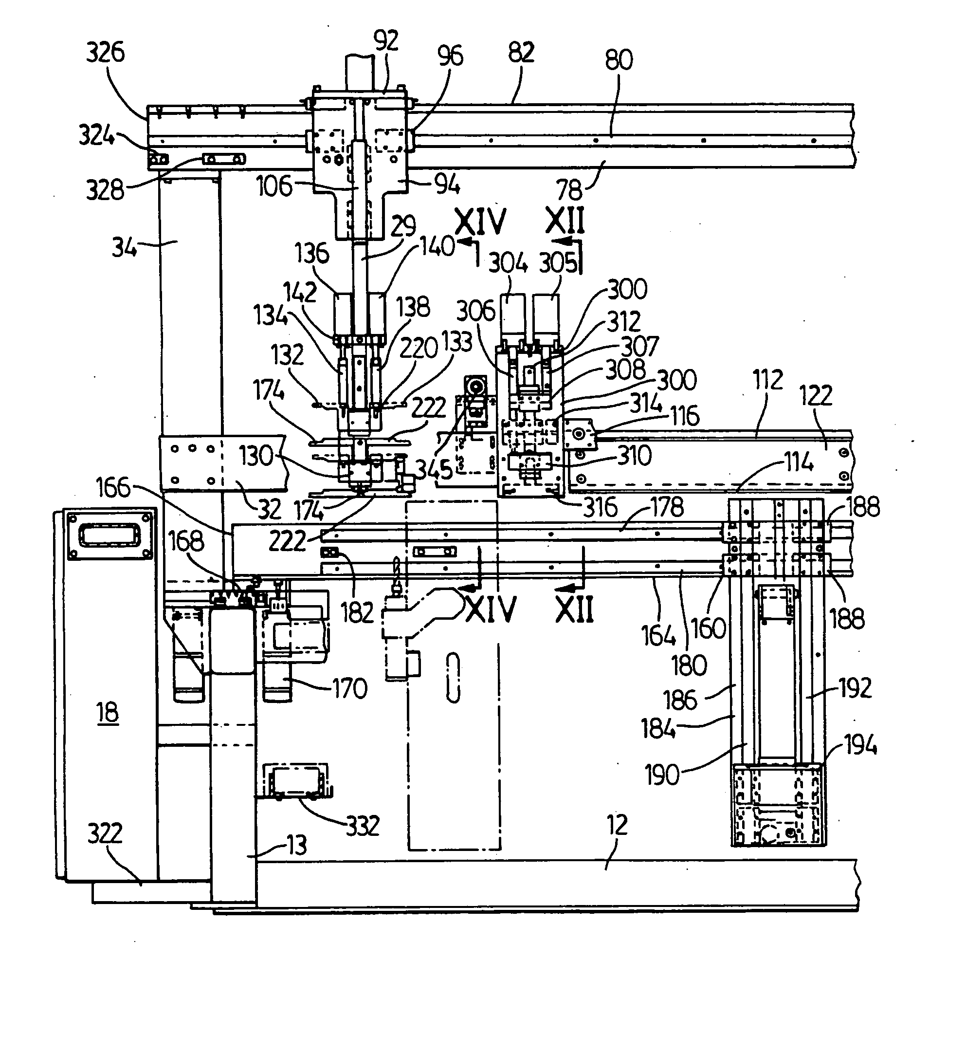
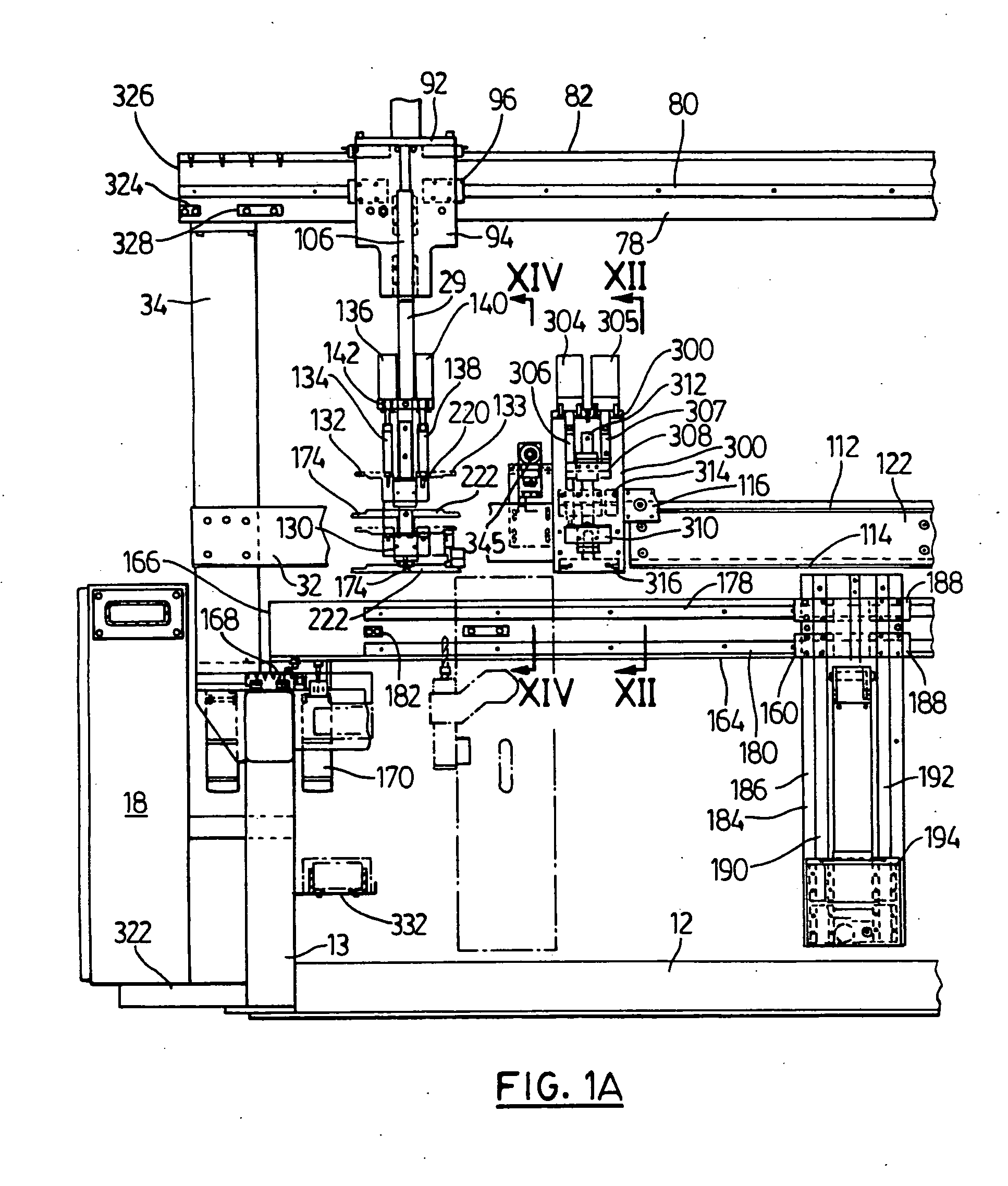
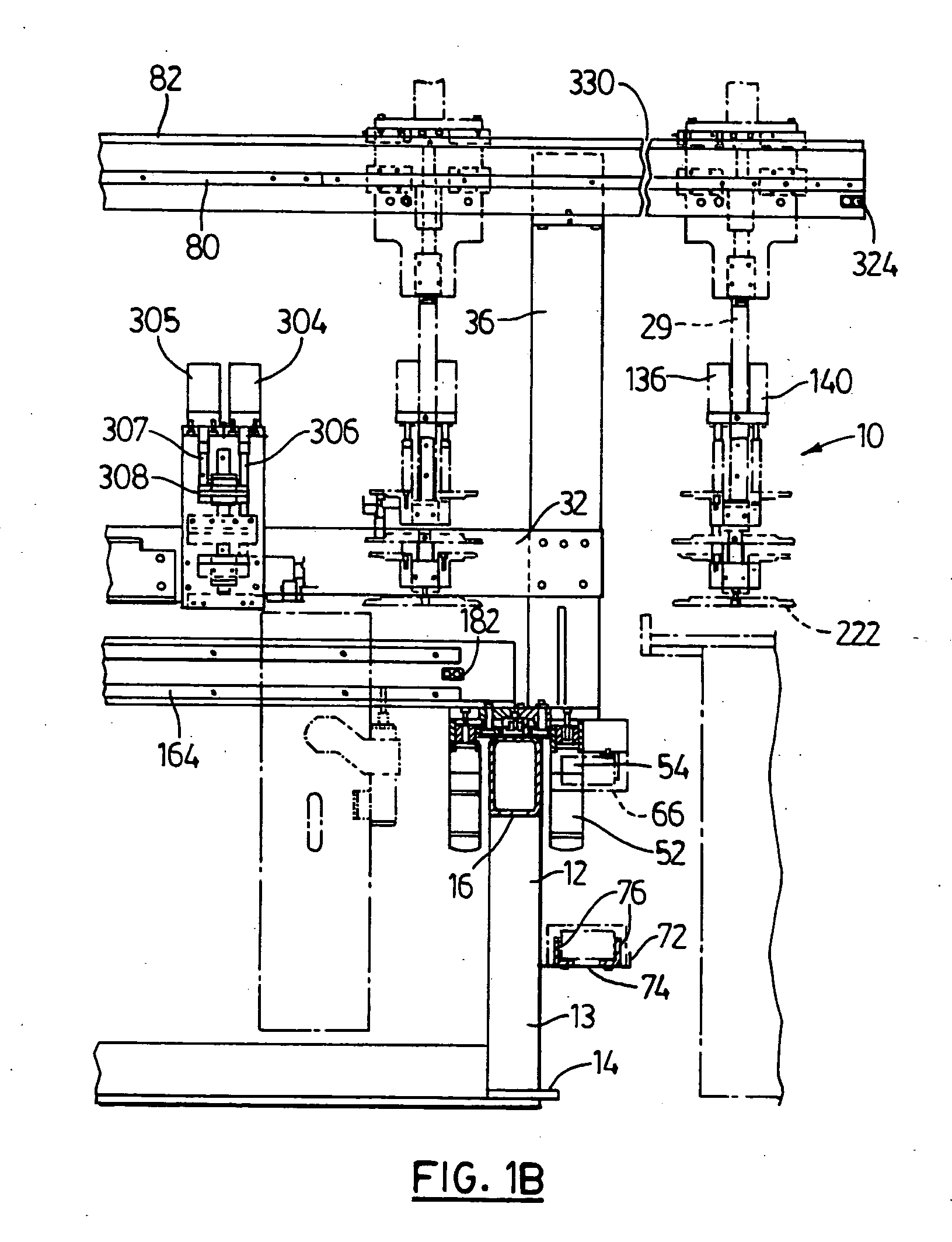
[0036] Referring initially to FIG. 9 which illustrates a production line that incorporates a machine for carrying out machining operations constructed in accordance with the invention, this machine or apparatus indicated generally at 10 is able to carry out machining operations on rectangular frameworks, such as window frames and window sashes using one or more power tools. The machine 10 is shown by itself and in greater detail in FIGS. 1A, 1B, 2A, 2B and 3 of the drawings. This window frame processing machine is built on a base frame 12 having a length and a width that sits on the floor of the manufacturing plant. This base frame includes a number of upright tubular posts 13. Shown on the right side of FIG. 9 is a known type of four-point automated welding machine 11 capable of welding the four corners of two window frames or sashes, or a combination of a window frame and a sash, described generally herein as frameworks. Two window frames or sashes are indicated at 15 and 15′ in F...


PUM

PropertyMeasurementUnit
angleaaaaaaaaaa
lengthaaaaaaaaaa
lengthaaaaaaaaaa

Abstract

A production line and a method for carrying out machining and cleaning operations on rectangular framework, such as window frames, is provided. Initially, elongate plastic frame members are welded together in a plastic frame welding machine, thereby forming two rectangular frameworks located one above the other. These are moved to a framework processing machine along separate predetermined paths where the first path being located above the second path. The paths are provided by horizontally extending guide arrangements on the machine which has at least one power tool for carrying out machining operations, this tool being supported by a transporting mechanism capable of moving the tool both horizontally and vertically. Machining steps are carried out on the two frame works while they are held one above the other in the processing machine. The frameworks are then moved to a weld cleaning machine along respective upper and lower paths and further processing operations including weld cleaning steps are carried out in this machine.

Description

BACKGROUND OF THE INVENTION [0001] This invention relates to a method for manufacturing plastic frameworks and a machine for carrying out machining operations that can be used with this method. [0002] The use of four-head welding machines to form window frames and window sashes from elongate plastic sections is well known in the window manufacturing industry. This known machine, which welds the frames in a horizontal position, is capable of welding together two window frames at once in a preferred embodiment. After the frameworks have been welded, it generally is necessary to carry out certain machining and cleaning steps on the rectangular frames to prepare them for use as a window or sash. For example, it is commonly necessary to drill holes or to cut slots in the frames in order to prepare them for window hardware such as hinges and window opening mechanisms. Also, because there is generally excess weld material at the four corners of each frame as a result of the welding process...

Claims


Application Information

Patent Timeline
Patent Type & Authority Applications(United States)
IPC IPC(8): B21D39/03B23P11/00B23P23/02B29D12/00
CPCB23P23/02Y10T29/49829Y10T29/53048Y10T408/93Y10T29/534Y10T29/5136Y10T408/38Y10T29/49831Y10T29/5191Y10T408/52Y10T409/307672Y10T408/91Y10T29/49828
Inventor RAMNAUTH, VINODEGIMELSHTEIN, LEON
Owner PRO LINE AUTOMATION SYST
Why Eureka
Try Eureka