Confocal laser scanning microscopy apparatus

a laser scanning and microscopy technology, applied in the direction of optical radiation measurement, fluorescence/phosphorescence, luminescent dosimeter, etc., can solve the problem of needing to de-scanning the laser beam

Inactive Publication Date: 2005-11-24
INST NAT DE LA SANTE & DE LA RECHERCHE MEDICALE (INSERM)
View PDF4 Cites 35 Cited by
  • Summary
  • Abstract
  • Description
  • Claims
  • Application Information

AI Technical Summary

Problems solved by technology

One of the drawbacks of such microscopy apparatus is the need for de-scanning

Method used


Image

  • Confocal laser scanning microscopy apparatus
  • Confocal laser scanning microscopy apparatus
  • Confocal laser scanning microscopy apparatus

Examples


Embodiment Construction

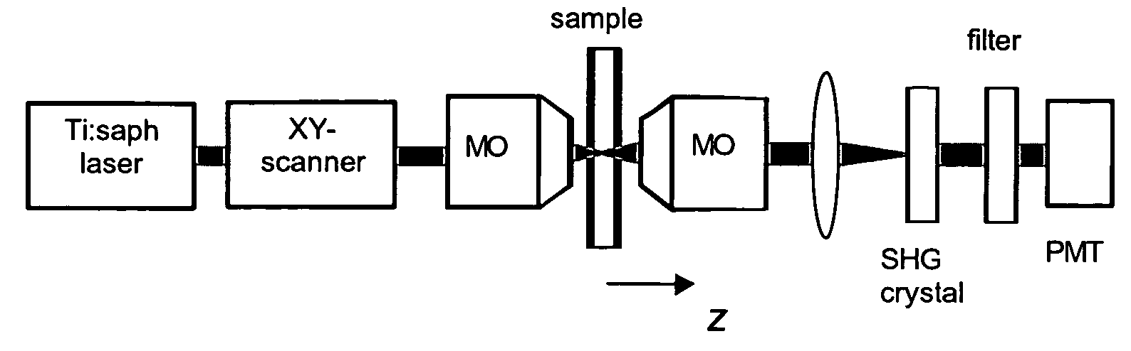
[0031] The present invention concerns a transmission-mode confocal scanning laser microscope system based on the use of second harmonic generation (SHG) for signal detection. This method exploits the quadratic intensity dependence of SHG to preferentially reveal unscattered signal light and reject out-of-focus scattered background. The SHG crystal plays the role of a virtual pinhole that remains self-aligned without a need for de-scanning.

[0032] Usually, confocal laser scanning microscopy (CLSM) is based on the use of a pinhole in the detection path to provide 3-dimensional image resolution and enhanced background rejection. In the usual CLSM implementation, detected light is de-scanned so that the pinhole effectively tracks the position of the laser focus at the sample. Such de-scanning is readily accomplished in a reflection configuration by retracing the signal path through the laser scanning optics. In a transmission configuration, however, de-scanning is technically much more ...


PUM


Abstract

The present invention concerns a confocal laser scanning microscopy apparatus, comprising: means for emitting a laser beam; means for scanning this laser beam in at least two directions onto an observed sample; means for generating a non linear light signal from the transmitted laser light, these non linear light signal generating means being disposed in the light path between the observed sample and detecting means which are adapted for detecting said non linear light signal.

Description

[0001] The present invention claims priority to U.S. 60 / 539254, which was filed on 26 Jan. 2004.BACKGROUND OF THE INVENTION [0002] The present invention concerns a confocal laser scanning microscopy apparatus, notably a transmission confocal laser scanning microscopy apparatus. [0003] Such microscopy apparatus exist and are for example described in the U.S. Pat. No. 3,013,467, or in “Theory and Practice of Scanning Optical Microscopy”, Academic press, London, 1984, by T. Wilson and C. Sheppard. [0004] One of the drawbacks of such microscopy apparatus is the need for de-scanning the laser beam since such aparatus comprise a pinhole in the detection path. SUMMARY OF THE INVENTION [0005] The present invention improves such known microscopy apparatus by providing a confocal laser scanning microscopy apparatus, comprising [0006] means for emitting a laser beam; [0007] means for scanning this laser beam in at least two directions onto an observed sample; [0008] means for generating a non ...

Claims


Application Information

Patent Timeline
IPC IPC(8): G01N21/64G02B21/00
CPCG02B21/0076G02B21/006
Inventor MERTZ, JEROMEYANG, CHANGHUEIMOREAUX, LAURENTPONS, THOMAS
Owner INST NAT DE LA SANTE & DE LA RECHERCHE MEDICALE (INSERM)
Why Eureka
Try Eureka