
Analog buffer, display device having the same, and method of driving the same

a technology of analog buffer and display device, which is applied in the direction of code conversion, pulse technique, instruments, etc., can solve the problems of increasing error voltage verror, increasing capacitances cgs and cgd, and requiring a more complex manufacturing process of poly silicon type lcd devices, etc., to reduce the size of source driving circuits

Active Publication Date: 2005-11-24
SAMSUNG DISPLAY CO LTD
View PDF1 Cites 27 Cited by
  • Summary
  • Abstract
  • Description
  • Claims
  • Application Information

AI Technical Summary

Benefits of technology

The present invention provides an analog buffer that can stabilize the output voltage during the manufacturing process of transistors. The analog buffer can also reduce the size of the source driving circuit. The invention also provides a display device with the analog buffer and a method of driving the analog buffer. The analog buffer includes a comparator and a transistor that can compare the input voltage with the analog voltage and turn on or off to charge or discharge the load accordingly. This technology ensures stable voltage output and reduces the size of the source driving circuit.

Problems solved by technology

However, the poly silicon type LCD device requires a more complex manufacturing process.
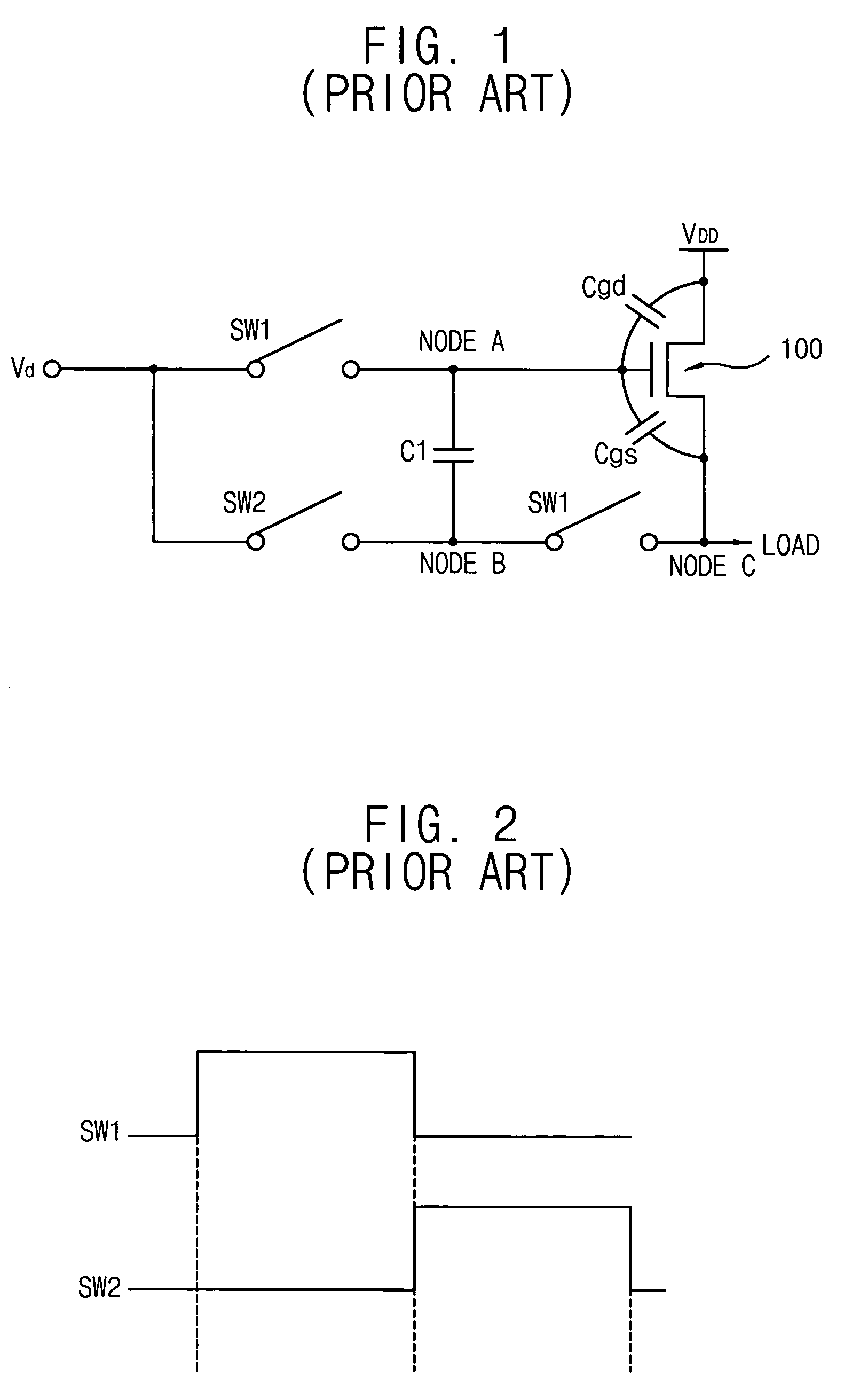
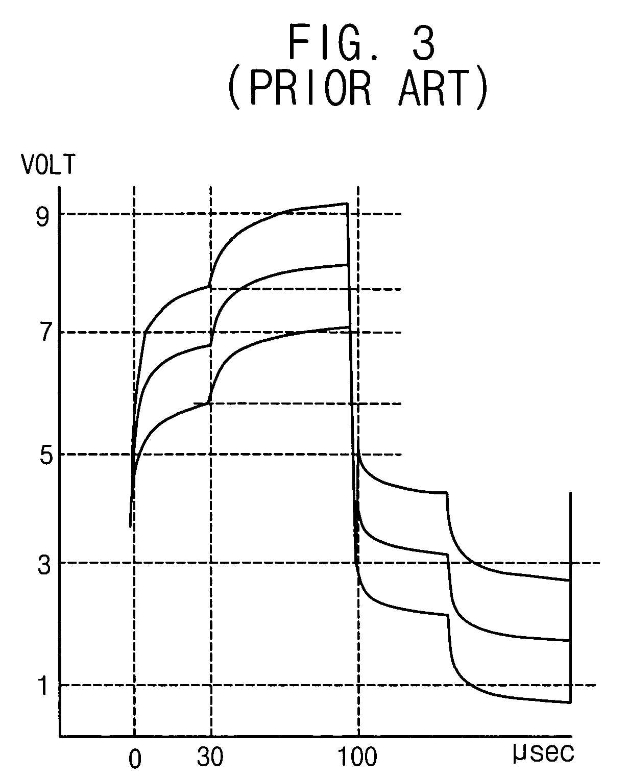
Therefore, the source follower in FIG. 1 is typically not used in an LCD device that requires a short time for driving source lines to display moving pictures.
However, when the channel width of the driver TFT 100 increases, the parasitic capacitances Cgs and Cgd also increase thus increasing the error voltage Verror.
As described above, the source follower requires a long time for driving source lines as one source follower drives one source line to reduce operation time.
However, it is difficult to form a poly-Si TFT having a large size and width of one pixel using LTPS because the size of the poly-Si TFT is greater than the width of one pixel.

Method used


Image

  • Analog buffer, display device having the same, and method of driving the same
  • Analog buffer, display device having the same, and method of driving the same
  • Analog buffer, display device having the same, and method of driving the same

Examples


Embodiment Construction

[0050] It should be understood that the exemplary embodiments of the present invention described below may be modified in many different ways without departing from the inventive principles disclosed herein, and the scope of the present invention is therefore not limited to these particular embodiments. Rather, these embodiments are provided so that this disclosure will be thorough and complete, and will fully convey the concept of the invention to those skilled in the art by way of example and not of limitation.

[0051] Hereinafter, the exemplary embodiments of the present invention will be described in detail with reference to the accompanying drawings.

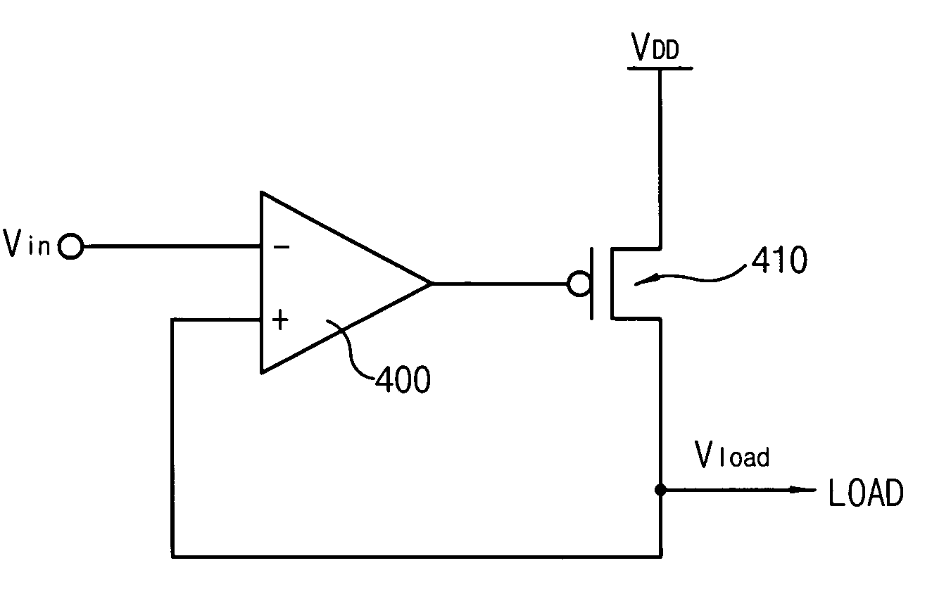
[0052]FIG. 4 is a conceptual circuit diagram illustrating an analog buffer according to an exemplary embodiment of the present invention. Referring to FIG. 4, an analog buffer includes a comparator 400 and a driver thin-film-transistor (TFT) 410 for driving loads.

[0053] The comparator 400 includes a negative terminal, a positive te...


PUM

PropertyMeasurementUnit
voltageaaaaaaaaaa
voltageaaaaaaaaaa
voltageaaaaaaaaaa

Abstract

An analog buffer, display device having the same and a method of drving the same are provided. The analog buffer applies an analog voltage to a load. The analog buffer includes a comparator and a transistor. The comparator is configured to compare an input voltage provided from an external device with the analog voltage applied to the load. The transistor is turned on to electrically charge the load when the analog voltage is lower than the input voltage or turned on to electrically discharge the load when the analog voltage is higher than the input voltage, and turned off when the analog voltage becomes substantially the same as the input voltage.

Description

CROSS-REFERENCE TO RELATED APPLICATION [0001] This application claims priority to Korean Patent Application No. 2004-33083 filed on May 11, 2004, the contents of which are herein incorporated by reference in its entirety. TECHNICAL FIELD [0002] The present invention relates to an analog buffer, a display device having the analog buffer, and a method of driving the analog buffer, and more particularly, to an analog buffer for high gray scale and high resolution applications. DESCRIPTION OF THE RELATED ART [0003] Information processing apparatuses having various functions and shapes are increasingly being developed. These information processing apparatuses typically use a display device such as a liquid crystal display (LCD) to display the information processed therein. An LCD device has many merits, for example, it is lightweight, and thin, has low power consumption and is capable of displaying high resolution images. [0004] The LCD device may be classified as either a poly silicon t...

Claims


Application Information

Patent Timeline
Patent Type & Authority Applications(United States)
IPC IPC(8): G09G3/20G02F1/133G09G3/36H03F3/00H03F3/50H03F3/70H03K5/08H03K19/00H03M1/66
CPCG09G3/3688H03F3/505H03F3/005H03K19/00
Inventor KIM, CHEOL-MINKIM, HYUN-JAEKIM, IL-GONMOON, KOOK-CHULKIM, CHUL-HOPARK, KEE-CHANLEE, SU-GYEONGPARK, TAE-HYEONGCHOI, JIN-YOUNGSHIM, HYUN-SOOKKWON, OH-KYONG
Owner SAMSUNG DISPLAY CO LTD
Learn More