Image compression device, image output device, image decompression device, printer, image processing device, copier, image compression method, image decompression method, image processing program, and storage medium storing the image processing program

a technology of image data and decompression device, which is applied in the field of image data decompression device, image output device, image decompression method, image processing program, etc., can solve the problems of low image segmentation accuracy, low reliability or faithfulness of image reproduction, and image data decompression after lossy-compression usually has distortion from original image data

Inactive Publication Date: 2005-11-24
SHARP KK
View PDF11 Cites 25 Cited by
  • Summary
  • Abstract
  • Description
  • Claims
  • Application Information

AI Technical Summary

Benefits of technology

[0007] An object of the present invention is to provide an image compression device capable of decreasing a size of a signal indicating a result of segmentation, generated toge

Problems solved by technology

Incidentally, image data decompressed after it was lossy-compressed usually has distortion from original image data.
Therefore, there is a low reliability or faithfulness in image reproduction.
This is because image segmentation is performed on the basis of decompressed image data (CMYK data), which gi

Method used


Image

  • Image compression device, image output device, image decompression device, printer, image processing device, copier, image compression method, image decompression method, image processing program, and storage medium storing the image processing program
  • Image compression device, image output device, image decompression device, printer, image processing device, copier, image compression method, image decompression method, image processing program, and storage medium storing the image processing program
  • Image compression device, image output device, image decompression device, printer, image processing device, copier, image compression method, image decompression method, image processing program, and storage medium storing the image processing program

Examples


Embodiment Construction

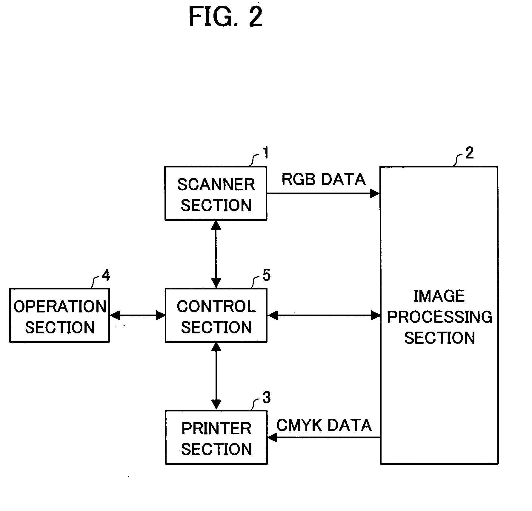
[0027] The following will describe one embodiment of the present invention. FIG. 2 is an explanatory diagram illustrating a configuration of a color digital copier (present copier) according to the present embodiment. As illustrated in FIG. 2, the present copier includes a scanner section 1, an image processing section 2, and a printer 3.

[0028] The scanner section (image output device) 1 includes an optical scanning unit, a document setting stage, CCD (Charge Coupled Device), and others (none of the components are shown). The scanner section 1 reads an optical image reflected from a document through the CCD so as to output RGB (R: red, G: green, B: blue) image data (RGB data).

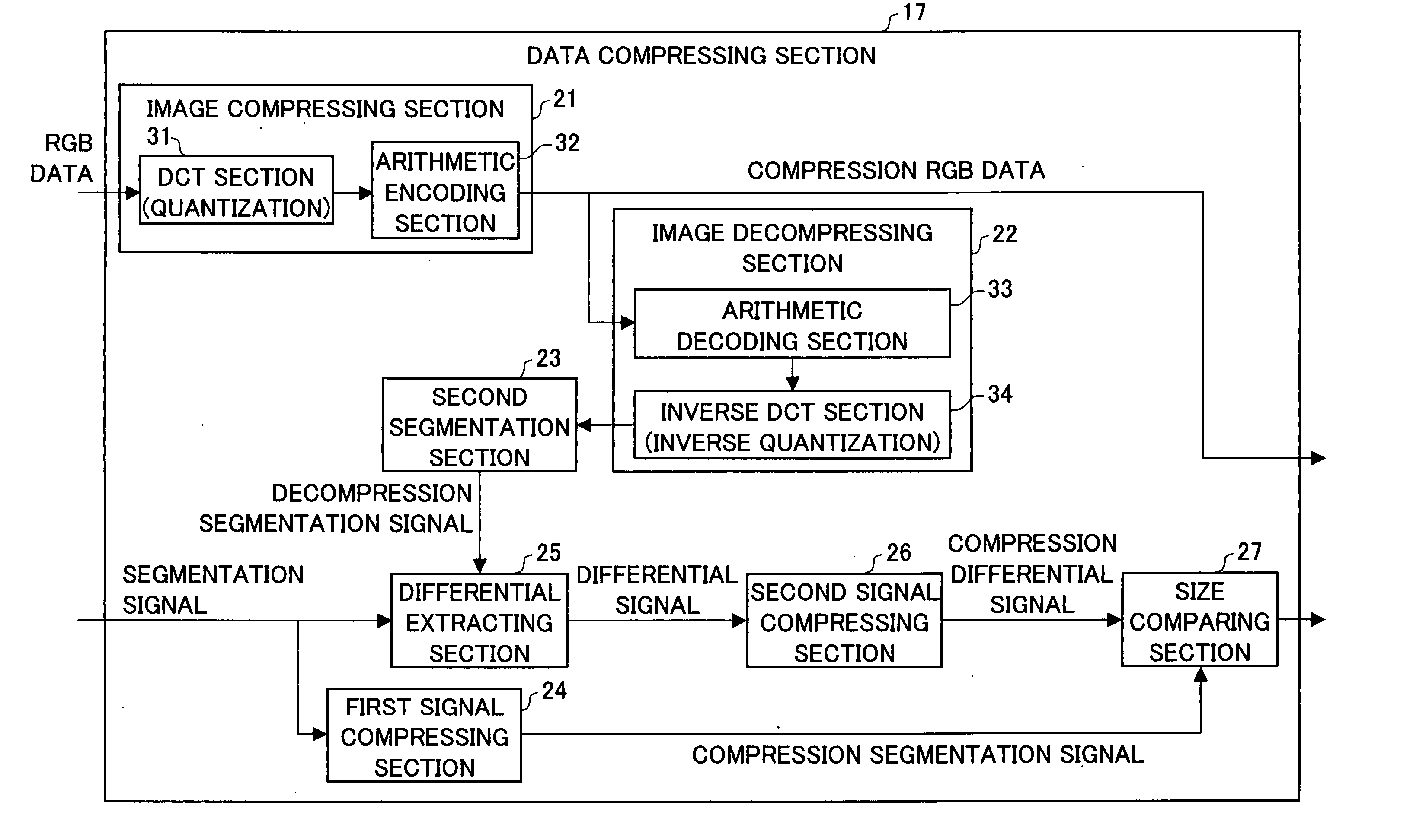
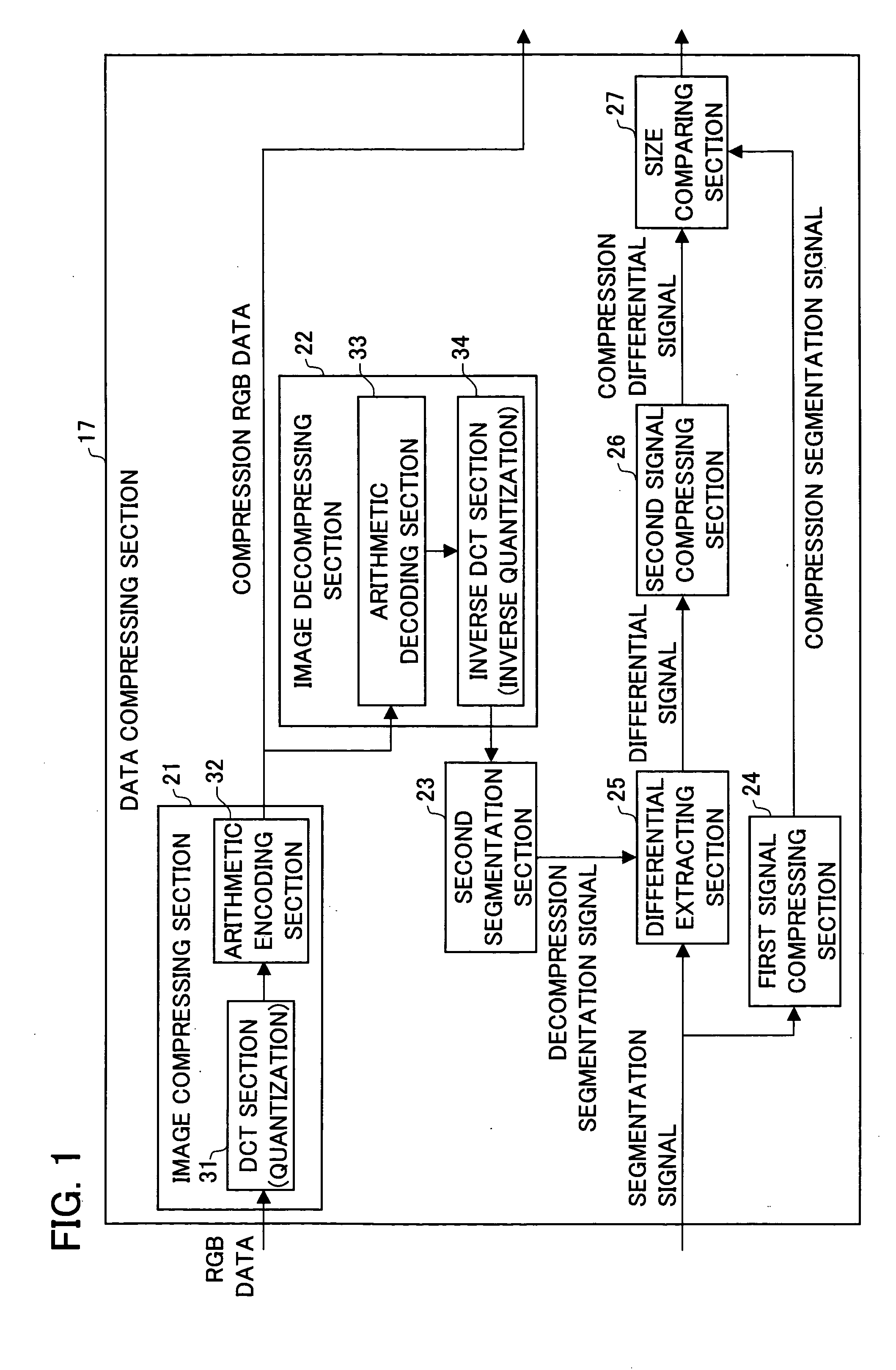
[0029] The image processing section (image processing device) 2 stores RGB data, outputted from the scanner section 1, under compression. Further, the image processing section 2 has a function of converting compressed RGB data (compression RGB data) into CMYK digital image data (CMYK data) suitable for printi...


PUM


Abstract

In a data compressing section, an image decompressing section decompresses compression RGB data, obtained by lossy compression, to generate decompression RGB data. A second segmentation section generates a decompression segmentation signal. Further, a differential extracting section generates a differential signal that indicates a differential between the segmentation signal and the decompression segmentation signal. A second signal compressing section generates a compression differential signal. Then, this compression differential signal is outputted as storage-use segmentation signal (signal indicating segmentation information), to a data storage section, together with the compression RGB data. The compression differential signal is smaller in size than the segmentation signal. This allows for reduction of a time required for data output and reduction of a required storage space.

Description

[0001] This Nonprovisional application claims priority under 35 U.S.C. § 119(a) on Patent Application No. 2004 / 149662 filed in Japan on May 19, 2004, the entire contents of which are hereby incorporated by reference. FIELD OF THE INVENTION [0002] The present invention relates to an image compression device which performs lossy compression on original image data and a decompression device which decompress lossy-compressed image data. BACKGROUND OF THE INVENTION [0003] In a conventional printer, original image data (RGB data or the like) scanned by a scanner or externally inputted is stored into memory by using a technique of compressing original image data because this technique needs smaller amounts of memory space used. Compressed image data is printed (image-reproduced) in the following manner: the compressed image data is decompressed, the decompressed data is converted into CMYK data, and the CMYK data is outputted to the print engine. [0004] Japanese Laid-Open Patent Applicatio...

Claims


Application Information

Patent Timeline
IPC IPC(8): G06T9/00G06K9/36H04N1/41H04N1/413H04N1/64H04N19/36H04N19/60H04N19/625H04N19/63H04N19/90H04N19/91
CPCH04N1/642H04N19/30H04N19/23H04N19/60H04N19/63
Inventor OGAWA, KAZUMA
Owner SHARP KK
Why Eureka
Try Eureka