Block area wavelet transform picture encoding apparatus

a wavelet transform and picture technology, applied in the field of picture encoding methods and apparatuses, can solve the problems of block distortion peculiar to dct, subjective deterioration, and the inability to perform fine control for each specified area of the picture, and achieve the effect of accurately enabling picture quality control

Inactive Publication Date: 2005-11-24
SONY CORP
View PDF13 Cites 8 Cited by
  • Summary
  • Abstract
  • Description
  • Claims
  • Application Information

AI Technical Summary

Benefits of technology

[0011] It is therefore an object of the present invention to provide a method and apparatus in which picture quality control from one partial area to another, that has so far been retained to be difficult, can be realized by a wavelet transform encoder to permit accurate picture quality control to improve the subjective picture quality as well as to allow to cope with both still and moving pictures by a sole encoder.
[0017] Moreover, according to the present invention, the quantization coefficients are multiplied by weighting coefficients provided at the outset for respective sub-bands, the respective quantization coefficients are resolved into bit planes, and the sequence of encoding the bit planes from the MSB to the LSB is made variable from one entropy encoding block to another to realize quantization control to enable picture quality control accurately.
[0018] In addition, the present invention can be applied to moving picture encoding apparatus adapted for coping with plural frames, so that an inexpensive apparatus may be provided which is able to cope with both still and moving pictures with a sole encoding unit.

Problems solved by technology

However, if, in this system, the number of encoding bits is diminished to a more or less extent, block distortion peculiar to DCT becomes outstanding to make subjective deterioration apparent.
(i) Since the wavelet transform usually executes transform on the entire picture, it is impossible to perform fine control for each specified area in a picture, such as macro-block based control in DCT of the MPEG or JPEG.
The technique has a defect that, (a) if the tile size is decreased, the encoding efficiency is lowered, and that (b) if the compression ratio is raised, discontinuities between neighboring tiles become outstanding to lower the subjective picture quality significantly.
In general, if the quantization step is increased, the number of bits generated is suppressed, however, the picture quality is deteriorated.

Method used


Image

  • Block area wavelet transform picture encoding apparatus
  • Block area wavelet transform picture encoding apparatus
  • Block area wavelet transform picture encoding apparatus

Examples


second embodiment

[0070] A second embodiment of the present invention is now explained. In this second embodiment, the entropy encoding unit 4 shown in FIG. 1 is constructed so that the quantization coefficients in a block are arranged into a bit plane composed of binary data, arithmetic encoding is executed depending upon the occurrence probability distribution of the symbols of each sub-bit plane and the probability distribution is estimated only for data in a pre-set block.

[0071] Referring to FIG. 10, the bit plane is explained with reference to FIGS. 10a to 10c. FIG. 10a shows 4 vertical by 4 horizontal or 16 quantization coefficients, with +13, −6 and so forth indicating post-quantization coefficient values. These quantization coefficients are divided into absolute values and signs of plus and minus, with the absolute values being expanded into a bit plane from the MSB to the LSB. FIGS. 10b and 10c indicate bit planes of the absolute values and a bit plane of signs, respectively. The coefficien...

third embodiment

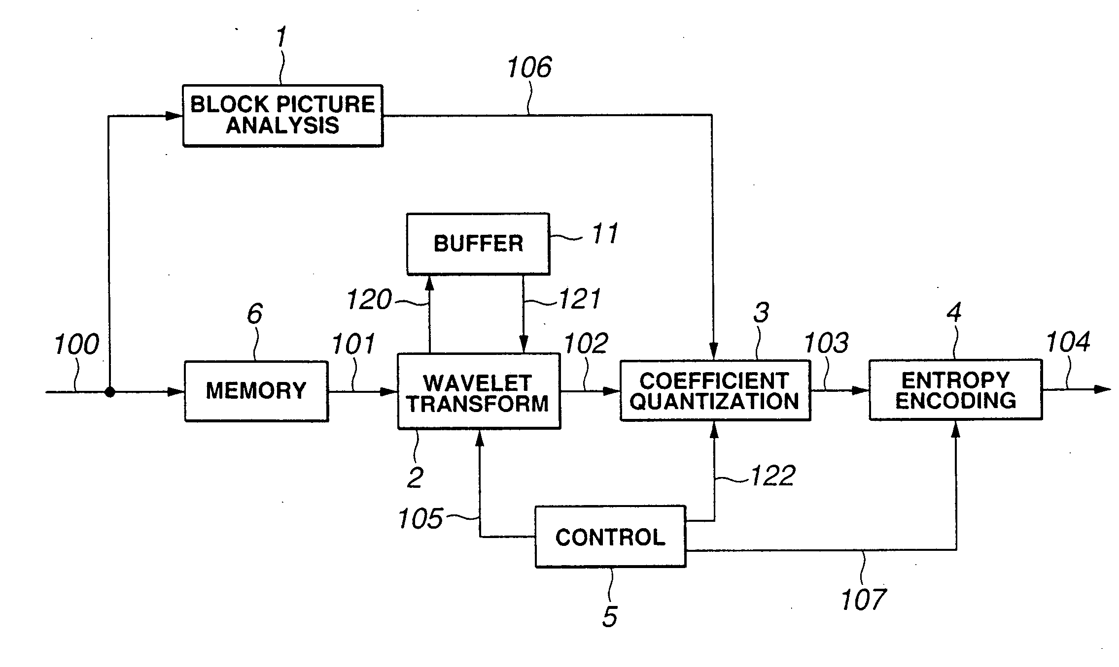
[0073] A picture encoding device, as a third embodiment of the present invention, is explained with reference to FIG. 11. The picture encoding device, shown in FIG. 11, is made up of a full picture memory unit 18 for storing the full picture of the input image, a full picture wavelet transform unit 7 for applying the wavelet transform filtering in the horizontal and vertical directions to the entire picture, a block coefficient extraction unit 8 for extracting wavelet transform coefficients corresponding to a specified block area forming a picture, a block coefficient quantizing unit 9 for quantizing the extracted wavelet transform coefficients, and an entropy encoding unit 4 for executing entropy encoding when the number of samples of generated quantization coefficients has reached a pre-set magnitude.

[0074] The first embodiment, already explained, differs from the third embodiment shown in FIG. 11 in that the first embodiment executes wavelet transform line by line, whereas the t...

fourth embodiment

[0081] The fourth embodiment of the present invention includes tile splitting means, upstream of the wavelet transform encoding unit, for splitting the input picture into plural rectangular tiles, and a downstream side encoding means for encoding picture data in each tile picture read out into a memory. An illustrative structure of the picture encoding device of the present fourth embodiment is shown in FIG. 12. The picture encoding device, shown in FIG. 12, is similar to the encoding device of FIG. 1 except that a tile splitting unit 10 is provided on the upstream side of the picture encoding device shown in FIG. 1. So, the encoding device, shown in FIG. 12, is not explained specifically.

[0082]FIG. 13 illustrates the operation of splitting the original picture into plural tiles and applying wavelet transform to each tile. In FIG. 13, solid lines indicate the boundaries of actual tiles and broken lines indicate the boundary of an area affected by wavelet transform filtering as late...


PUM


Abstract

In wavelet transform encoding, high-quality encoding is to be realized by enabling picture quality control from one fractional area to another. An input picture 100 is read out in an amount corresponding to a number of lines required for wavelet transform and buffered in a memory unit 6. The input picture then is wavelet transformed in a wavelet transform unit 2 and quantized in a coefficient quantizing unit 3. In quantizing wavelet transform coefficients, the wavelet transform coefficients are multiplied by weighting coefficients from one sub-band to another. The weighting coefficients are determined using the analysis information of a specified block area in a picture, such as motion information and texture fineness information. This enables fine quantization control in terms of a picture block as a unit.

Description

BACKGROUND OF THE INVENTION [0001] 1. Field of the Invention [0002] This invention relates to a picture encoding method and apparatus for encoding a still image or moving pictures using wavelet transform. [0003] 2. Description of Related Art [0004] Typical of the conventional representative picture compression systems is the JPEG (Joint Photographic Coding Experts Group) system standardized by ISO (International Organization for Standardization). This JPEG system is a system for compressing and encoding mainly a still picture using DCT (discrete cosine transform). This JPEG is known to give acceptable encoded and decoded pictures on the condition that a larger number of bits is allocated. However, if, in this system, the number of encoding bits is diminished to a more or less extent, block distortion peculiar to DCT becomes outstanding to make subjective deterioration apparent. [0005] Recently, such a system comprising splitting the frequency spectrum of a picture into plural bands ...

Claims


Application Information

Patent Timeline
Patent Type & Authority Applications(United States)
IPC IPC(8): H04N19/60G06K9/36G06K9/46G06T9/00H03M7/30H03M7/40H04N19/124H04N19/136H04N19/169H04N19/196H04N19/42H04N19/423H04N19/46H04N19/63H04N19/70H04N19/80H04N19/86
CPCH04N19/10H04N19/176H04N19/13H04N19/63H04N19/122H04N19/86H04N19/117H04N19/124H04N19/635H04N19/645H04N19/61
Inventor FUKUHARA, TAKAHIROKIMURA, SEIJI
Owner SONY CORP
Why Eureka
Try Eureka