Rolling bearing device and ring with sensor for the rolling bearing device
a technology of rolling bearing and sensor, which is applied in the direction of bearings, devices using electric/magnetic means, shafts, etc., can solve the problems of limiting the freedom of laying out parts, affecting the life of bearings, and bearings that are often splashed with water, so as to reduce the formation of artificial parts and be easily attached.
- Summary
- Abstract
- Description
- Claims
- Application Information
AI Technical Summary
Benefits of technology
Problems solved by technology
Method used
Image
Examples
first embodiment
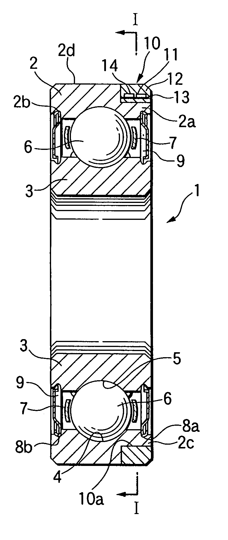
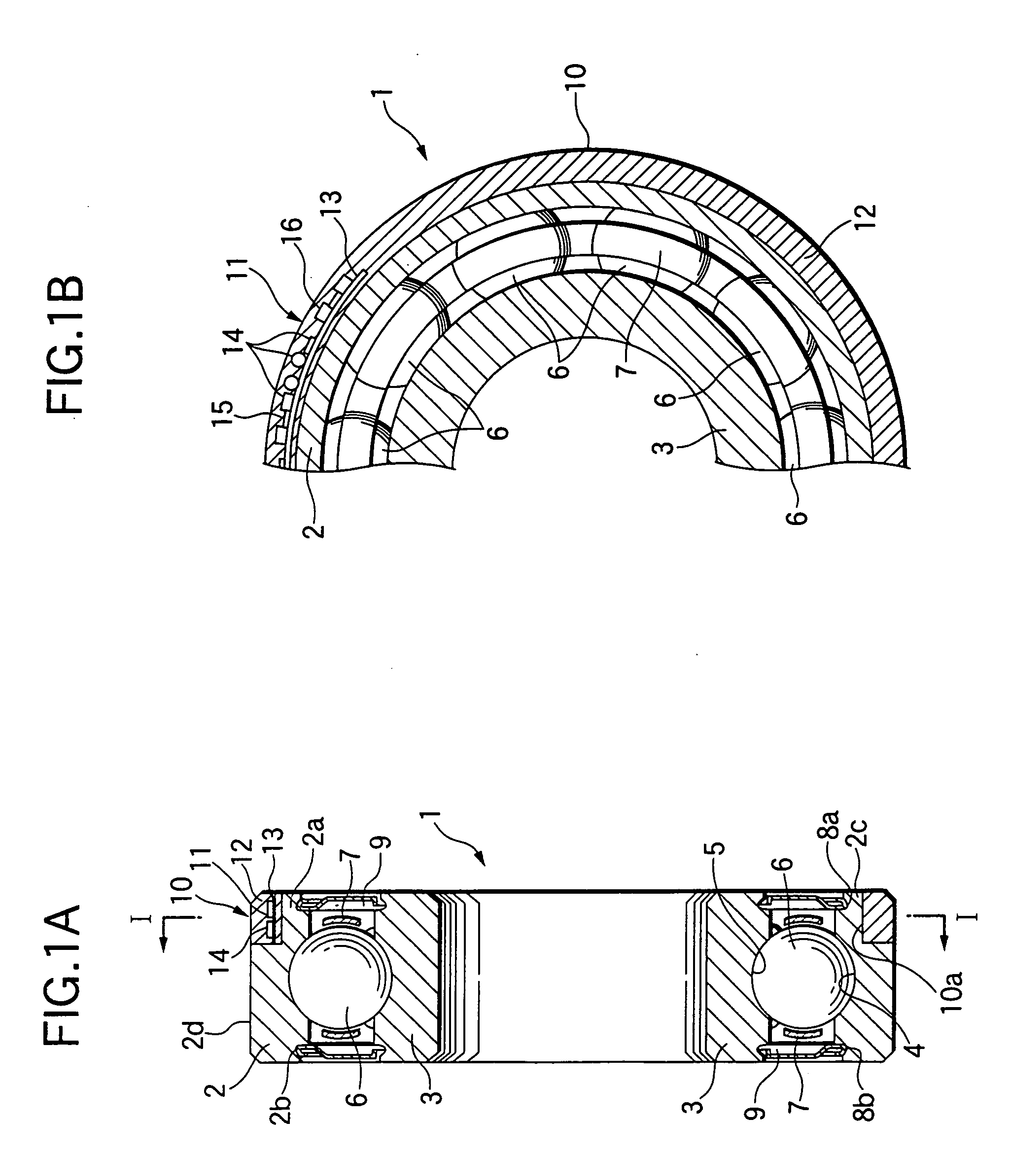
[0071] the present invention will be described with reference to FIGS. 1A and 1B. A bearing 1 shown in FIGS. 1A and 1B is a single-row deep groove ball bearing. The bearing 1 includes an outer ring 2 and an inner ring 3, which are examples of a bearing ring. An outer raceway 4, while being recessed, is formed at a central part of the inner peripheral surface of the outer ring 2. An inner raceway 5, while being recessed, is formed at a central part of the outer peripheral surface of the inner ring 3. A plurality of balls 6 as rolling elements are retained with a retainer 7 in the circumferential direction at equal intervals, while being equiangularly disposed and in rolling contact with the outer raceway 4 and the inner raceway 5. Shield mounting grooves 8a and 8b are respectively provided at the inner peripheral surfaces of both ends 2a and 2b of the outer ring 2 as viewed in the widthwise direction. Shields 9 are fitted to those grooves 8a and 8b.
[0072] An annular groove 10, as sh...
second embodiment
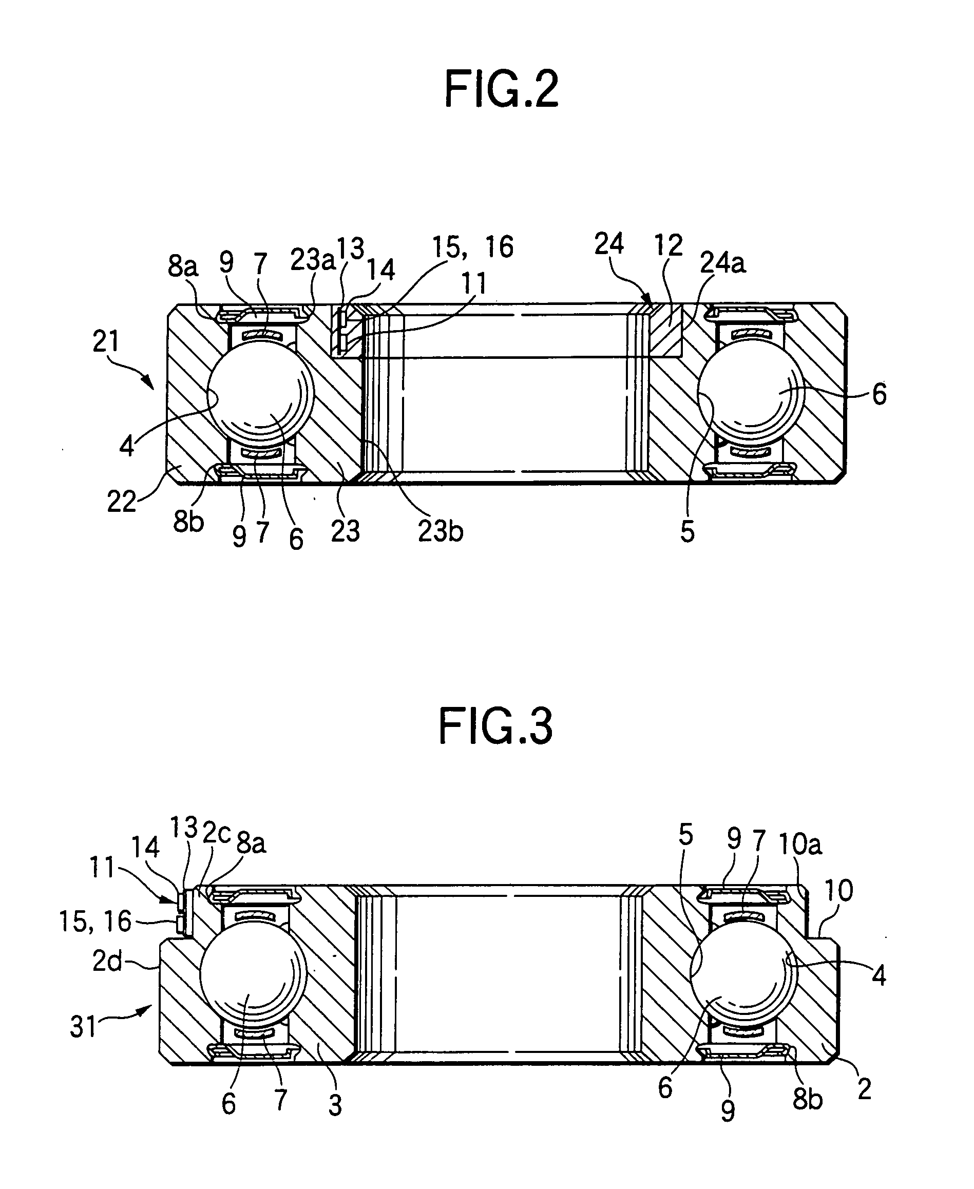
[0074] the invention will be described with reference to FIG. 2. In the bearing 21 as shown in FIG. 2, an annular groove 24 is formed entirely over the inner peripheral surface of an inner ring 23, viz., the annular groove is not formed in the outer ring 22. A sensor 11 is circumferentially disposed on the bottom surface 24a of the annular groove 24 in a state that the sensor 11 is located inside a prolongation of the side face 23a of the inner ring 23, but outside a prolongation of the inner peripheral surface 23b. The sensor 11 is molded by using an insulating material, e.g., a synthetic resin 12. The protecting synthetic resin 12 fills the annular groove 24, and is annular in shape. Incidentally, the synthetic resin 12 is provided for improving the performances of the dust-proof, water-proof and oil-proof. The end face and the inner peripheral surface of it are flush with the side face 23a and the inner peripheral surface 23b, while being continuous to the latter. To measure a te...
fifth embodiment
[0081] the invention will be described with reference to FIG. 5. A bearing 51 shown in FIG. 5 includes a surface-opposed generator 52, which is located between the outer ring 2 and the inner ring 3. The surface-opposed generator 52 includes a coil 53 and a magnet 54. A shield 9 is fitted into a groove 8a, which is formed in the inner peripheral surface in an end 2a of the outer ring 2 in the widthwise direction, and corresponds to the location of the annular groove 10. And, the coil 53 is mounted on the inner side (=surface facing balls 6) of the shield 9. The magnet 54 is mounted on a holding plate 55, while being disposed in association with the coil 53. The holding plate 55 is fitted into a holding-plate mounting groove 56, which is formed in the outer peripheral surface of an end 3a of the inner ring 3 in the width direction.
[0082] The generator 52 generates electricity and supplies it to the sensor 11. The remaining portion of the embodiment is substantially the same as the cor...
PUM
 Abstract
Description
Claims
Application Information
 - R&D
- Intellectual Property
- Life Sciences
- Materials
- Tech Scout
- Unparalleled Data Quality
- Higher Quality Content
- 60% Fewer Hallucinations
Browse by: Latest US Patents, China's latest patents, Technical Efficacy Thesaurus, Application Domain, Technology Topic, Popular Technical Reports.
© 2025 PatSnap. All rights reserved.Legal|Privacy policy|Modern Slavery Act Transparency Statement|Sitemap|About US| Contact US: help@patsnap.com


