Fuel reformer system with improved water transfer

a technology of reformer system and water transfer, which is applied in the direction of fuel cells, electrical equipment, electrochemical generators, etc., can solve the problems of increasing the complexity of the resulting reformer system, increasing the complexity of the reformer system, and increasing the overall efficiency of the system, so as to reduce or eliminate the need for liquid water handling, improve the recovery and utilization of water vapor and/or heat energy, and reduce energy requirements and component complexity

Inactive Publication Date: 2005-11-24
GM GLOBAL TECH OPERATIONS LLC
View PDF18 Cites 49 Cited by
  • Summary
  • Abstract
  • Description
  • Claims
  • Application Information

AI Technical Summary

Benefits of technology

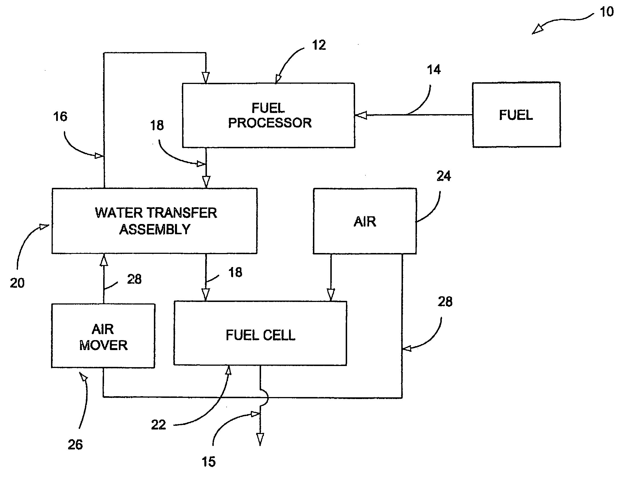
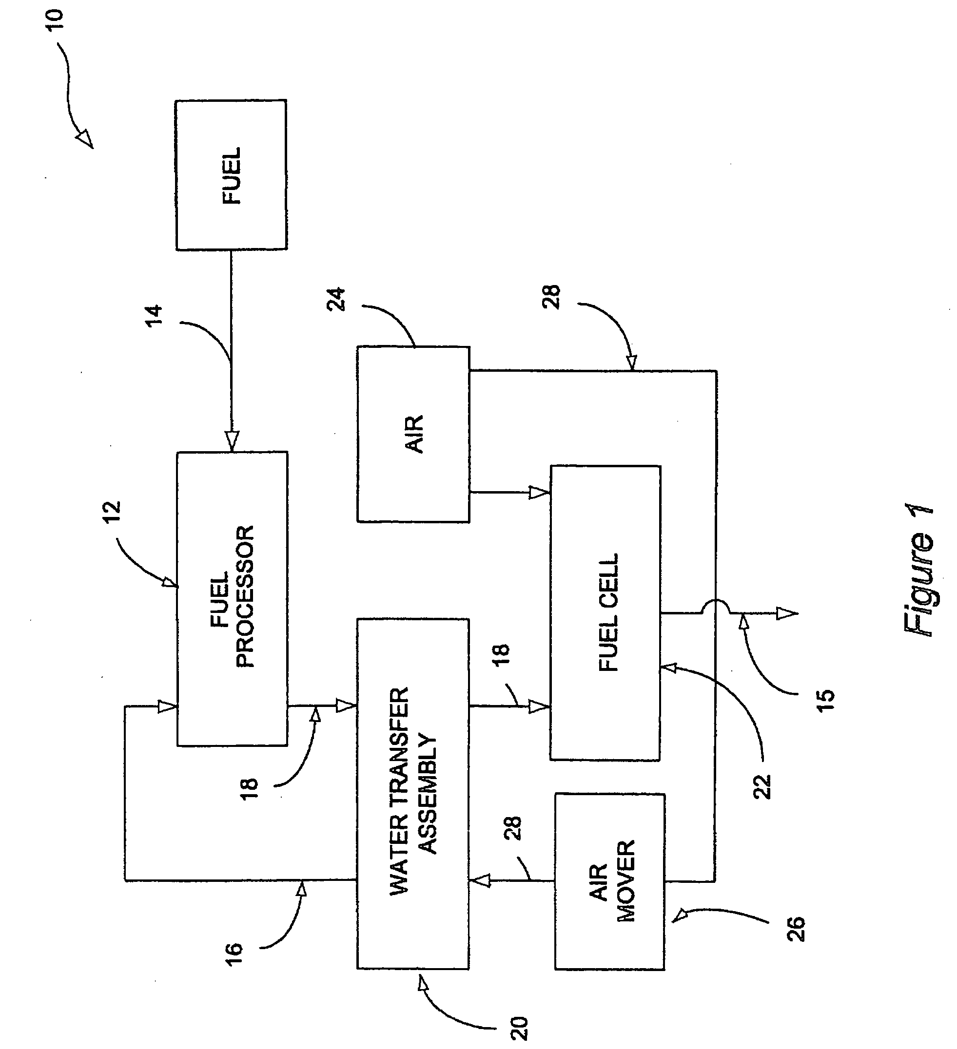
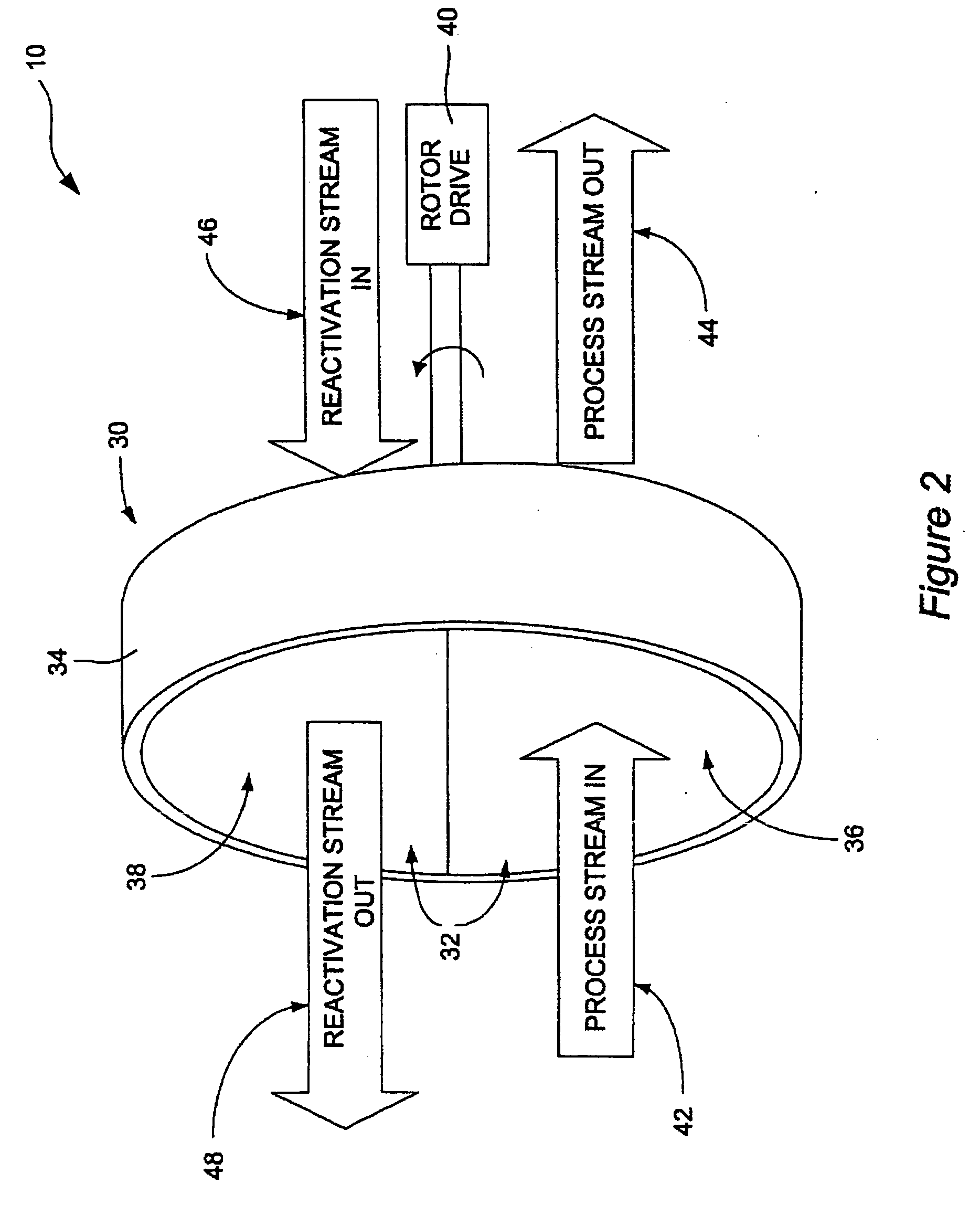
[0010] The present invention provides several embodiments for a hydrocarbon fuel reformer system that improves the recovery and utilization of the water vapor and/or the heat energy within the reformer system while decreasing or eliminating the need for handling liquid water. In particular, the present invention utilizes a desiccant to collect water vapor from a process stream and transfer the water to a reactivation stream that is then fed back into the reform

Problems solved by technology

The use of multiple heat exchangers increases the complexity of the resulting reformer system.
Moreover, the liquid condensate produced by the heat exchangers must be vaporized before being fed back into the reformer or fuel cell, thereby creating an additional energy load and decreasing the overall efficiency of

Method used


Image

  • Fuel reformer system with improved water transfer
  • Fuel reformer system with improved water transfer
  • Fuel reformer system with improved water transfer

Examples


fourth embodiment

[0035] The dehumidified fuel cell exhaust 120 is then fed into the combustor 124 to consume any residual hydrogen or fuel vapor and produce a combustor exhaust stream 126. In this fourth embodiment, the combustor exhaust stream 126 and an oxidant stream 128 may then both be fed into a water transfer assembly 134. The exhaust stream 126 and / or the oxidant stream 128 may pass directly into the water transfer assembly 134 or be conditioned by an intermediate heat exchanger as illustrated in FIG. 3. In the water transfer assembly 134, water vapor from the combustor exhaust 126 is again transferred to the oxidant stream 128 to produce a wet oxidant stream 116 that is fed into the fuel processor 112.

[0036] A fifth embodiment is illustrated in FIG. 6. This fifth embodiment again provides a hydrocarbon fuel cell plant 110 comprising a fuel processor 112 for reacting a hydrocarbon fuel feed stream 114 and an oxidant feed stream 116 to produce a hydrogen-containing reformate stream 118. As in...

fifth embodiment

[0037] Within the condensing heat exchanger 130, the fuel cell exhaust stream 120 is cooled to below its dew point, inducing the condensation of water vapor present in the fuel cell exhaust stream 120 to form a condensate consisting primarily of water. The condensate is first transferred to a water reservoir 142 and then to a humidifier 144 where it is used to add water vapor to a fuel cell feed stream, preferably the oxidant feed stream 140. The dehumidified or dry fuel cell exhaust stream 146 is then fed into the combustor 124 to consume any residual hydrogen or fuel vapor and produce a combustor exhaust stream 126. In this fifth embodiment, the combustor exhaust stream 126 and an oxidant stream 128 may then both be fed into a water transfer assembly 134, with or without passing through an intermediate heat exchanger. In the water transfer assembly 134, water vapor from the combustor exhaust 126 is again transferred to the oxidant stream 128 to produce a wet oxidant stream 116 tha...


PUM


Abstract

The present invention provides a hydrocarbon fuel reformer systems that improve the recovery and utilization of the water vapor and/or the heat energy within the reformer system. In a preferred embodiment, the present invention utilizes a desiccant matrix maintained in a water transfer assembly to collect, in a continuous manner, water from a process stream and transfer the water to a reactivation stream to return the water vapor to the reformer, with or without the use of a heat exchanger, and without requiring the collection and evaporation of liquid water.

Description

CROSS-REFERENCE TO RELATED APPLICATIONS [0001] This application claims the benefit of U.S. Provisional Application No. 60 / 572,032, filed on May 18, 2004, the disclosure of which is incorporated herein by reference.FIELD OF THE INVENTION [0002] This invention relates to reformer systems utilized for producing hydrogen from a hydrocarbon fuel, and more particularly to a reformer system having components configured to recover water vapor from a process gas stream and transfer the recovered water to a reactivation stream. Such reformer systems may be used to produce a hydrogen-rich reformate stream that becomes, in turn, the anode feed gas for a H2—O2 fuel cell stack. BACKGROUND OF THE INVENTION [0003] H2—O2 fuel cells separate the hydrogen (H2) fuel and an oxidant, typically oxygen from air, with an electrolyte. Within the fuel cell, the hydrogen gas separates into electrons and hydrogen ions (protons) at the anode. The hydrogen ions pass through the electrolyte to the cathode with the...

Claims


Application Information

Patent Timeline
IPC IPC(8): H01M8/04H01M8/06
CPCH01M8/04022H01M8/04141Y02E60/50H01M8/0612Y02E60/523H01M8/04171
Inventor FORTE, JAMESON R.
Owner GM GLOBAL TECH OPERATIONS LLC
Why Eureka
Try Eureka