

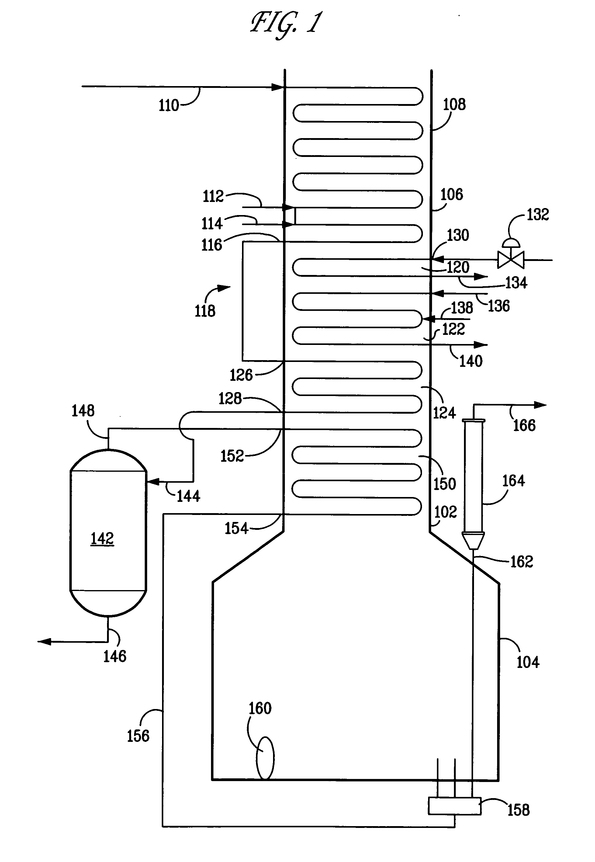
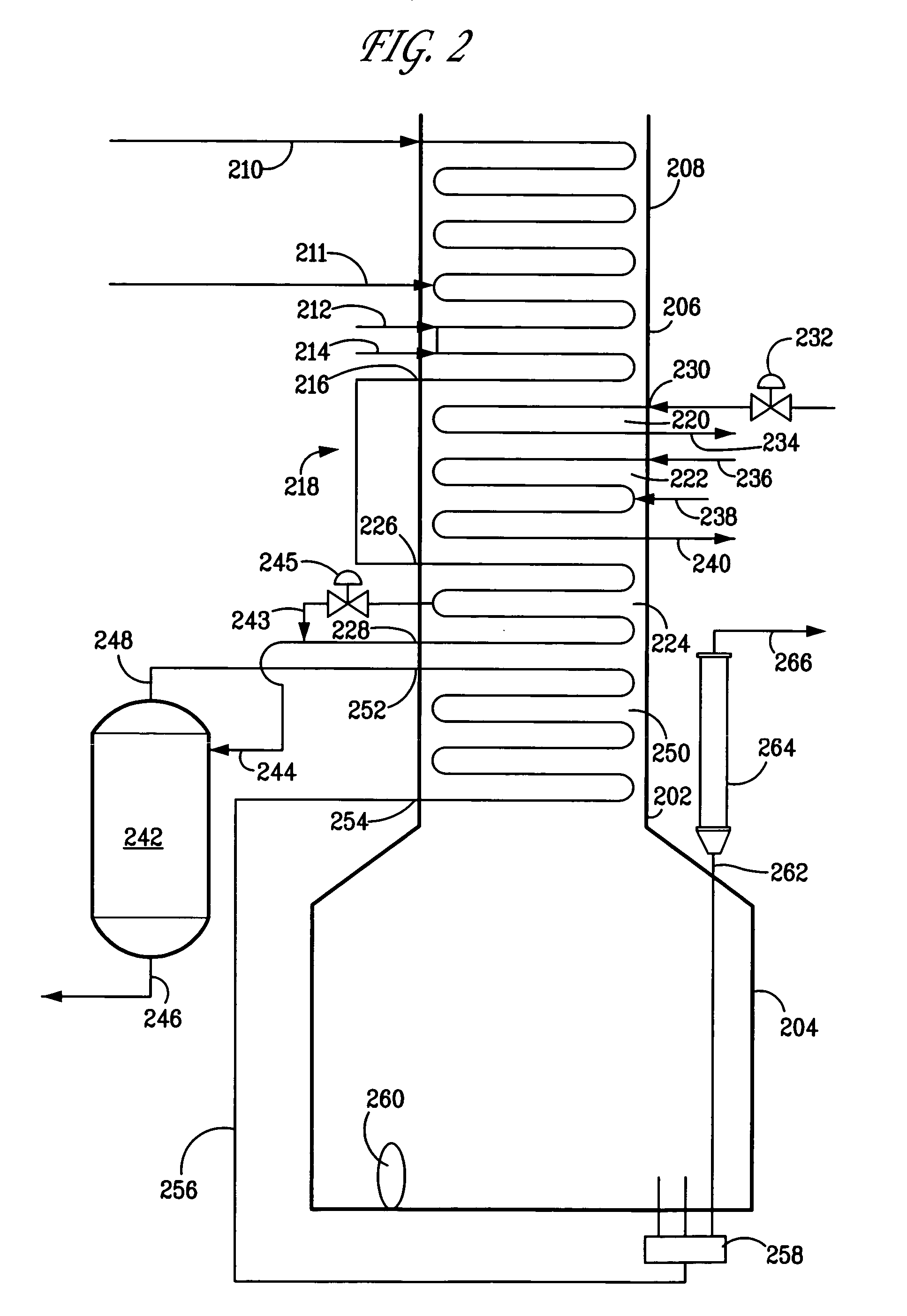
Apparatus and process for controlling temperature of heated feed directed to a flash drum whose overhead provides feed for cracking
a technology of heated feed and flash drum, which is applied in the cracking process of hydrocarbon oil, hydrocarbon oil treatment products, thermal non-catalytic cracking, etc., can solve the problems of moderate coking, rapid fouling of transfer line exchangers, contamination of naphthas and condensates, etc., and achieve greater heat content. , the effect of increasing the heat conten
- Summary
- Abstract
- Description
- Claims
- Application Information
AI Technical Summary
Benefits of technology
Problems solved by technology
Method used
Image

Examples
Embodiment Construction
[0019] Unless otherwise stated, all percentages, parts, ratios, etc. are by weight. Ordinarily, a reference to a compound or component includes the compound or component by itself, as well as in combination with other compounds or components, such as mixtures of compounds.
[0020] Further, when an amount, concentration, or other value or parameter is given as a list of upper preferable values and lower preferable values, this is to be understood as specifically disclosing all ranges formed from any pair of an upper preferred value and a lower preferred value, regardless of whether ranges are separately disclosed.
[0021] As used herein, resids are non-volatile components, e.g., the fraction of the hydrocarbon feed with a nominal boiling point above 590° C. (1100° F.) as measured by ASTM D-6352-98 or D-2887. This invention works very well with non-volatiles having a nominal boiling point above 760° C. (1400° F.). The boiling point distribution of the hydrocarbon feed is measured by Gas...
PUM
| Property | Measurement | Unit |
|---|---|---|
| temperatures | aaaaa | aaaaa |
| temperatures | aaaaa | aaaaa |
| temperatures | aaaaa | aaaaa |
Abstract
Description
Claims
Application Information