

Indirect evaporative cooling heat exchanger
a heat exchanger and evaporative cooling technology, applied in the direction of indirect heat exchangers, heating types, lighting and heating apparatus, etc., can solve the problems of long assembly period, high cost, and difficult repeatability of manufacturing methods, and achieve the effect of low cost and easy repeatability of manufacturing
- Summary
- Abstract
- Description
- Claims
- Application Information
AI Technical Summary
Benefits of technology
Problems solved by technology
Method used
Image

Examples
Embodiment Construction
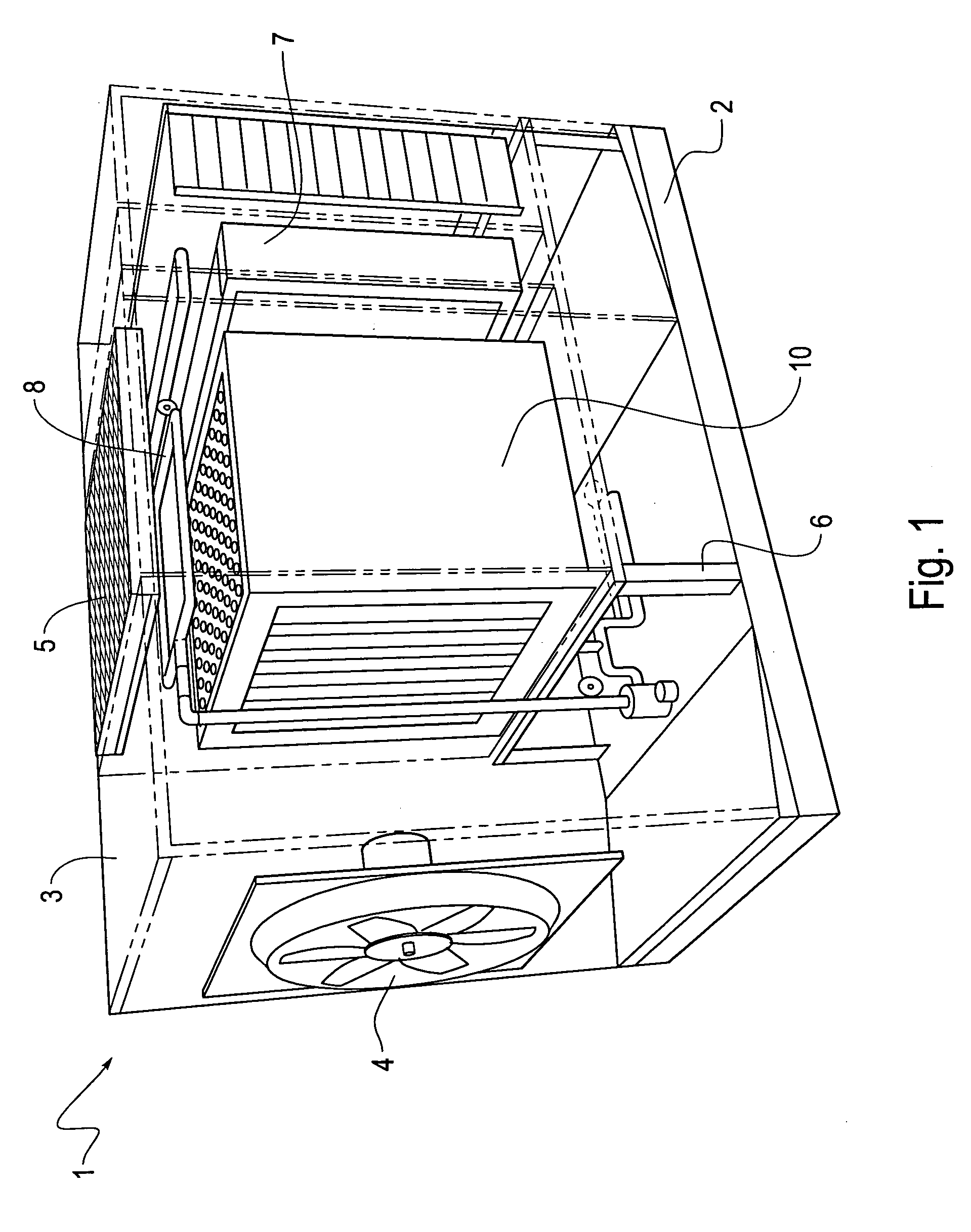
[0030]FIG. 1 is a perspective view of an indirect / direct evaporative cooling unit, including an indirect evaporative cooler heat exchanger, according to an exemplary embodiment of the invention. As shown in FIG. 1, an indirect / direct evaporative cooling unit 1 includes, a base portion 2, a frame 3, and an air intake fan 4 mounted in a wall of the frame 3 at one end of the unit 1. The intake fan 4 provides outside air to the unit 1. The unit 1 further includes an exhaust grate 5 mounted in the top of the unit 1 to allow high energy, unconditioned air to exit the unit 1.
[0031] A support frame 6 is mounted to the base portion 2 within the unit 1 to provide a mounting point for the indirect heat exchanger 10 and the direct cooling stage 7. A water distribution manifold 8 is disposed over the indirect heat exchanger 10 and the direct cooling stage 7 to deliver water thereto. In other words, the unit shown in FIG. 1 includes all the devices that are necessary for proper operation to cool...
PUM
| Property | Measurement | Unit |
|---|---|---|
| chord length | aaaaa | aaaaa |
| width | aaaaa | aaaaa |
| thickness | aaaaa | aaaaa |
Abstract
Description
Claims
Application Information