
Pressure regulator

a technology of pressure regulator and pressure regulator, which is applied in the direction of fluid pressure control, process and machine control, instruments, etc., can solve the problems of reducing secondary pressure, difficult to accurately provide a target secondary pressure with respect to a wide primary pressure range, and difficulty in appropriately positioning the two regulating valves. , to achieve the effect of simplifying the mechanism, good pressure regulation characteristics and simplifying the structur

Inactive Publication Date: 2005-12-01
TOKAI
View PDF5 Cites 27 Cited by
  • Summary
  • Abstract
  • Description
  • Claims
  • Application Information

AI Technical Summary

Benefits of technology

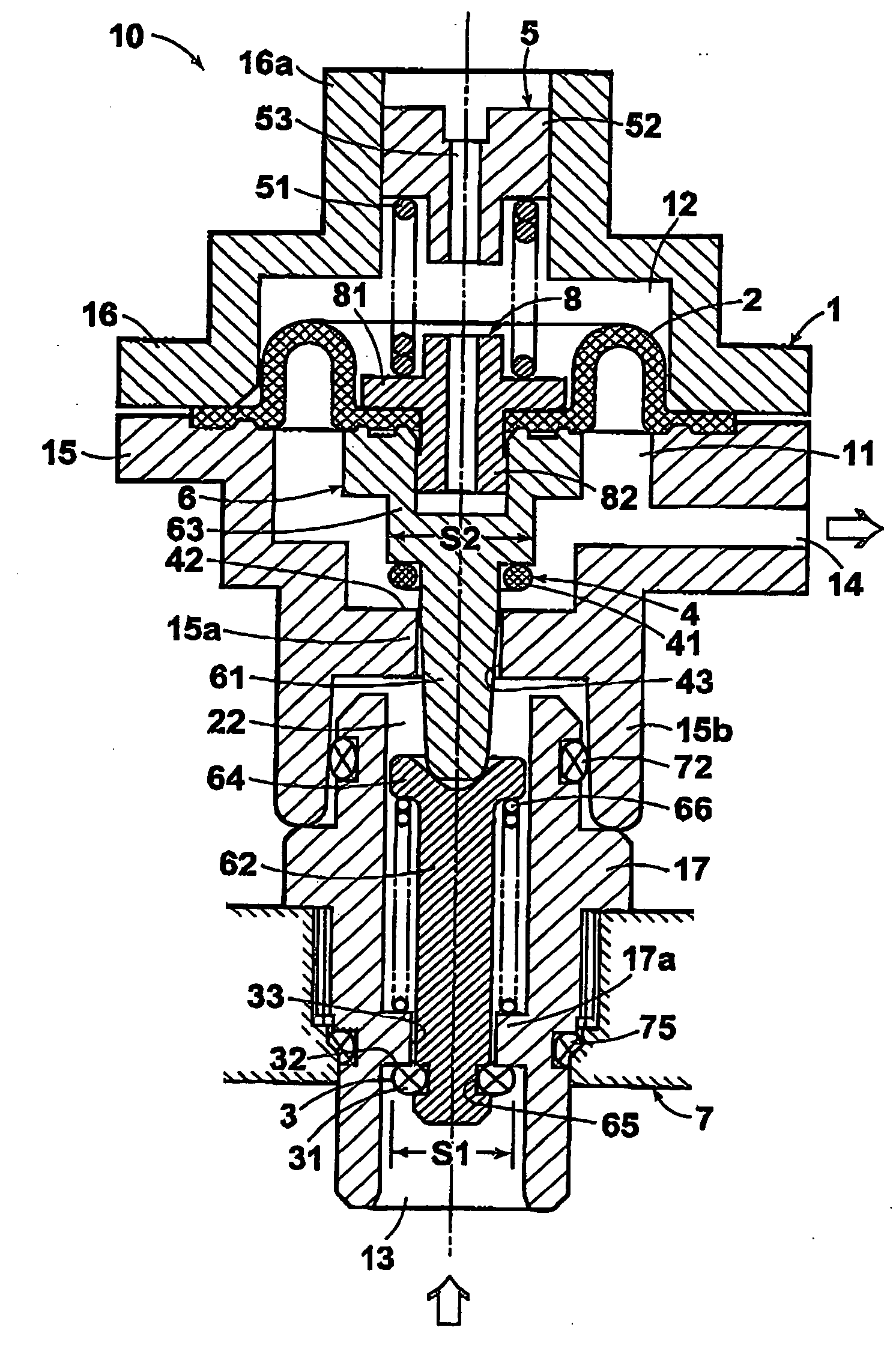
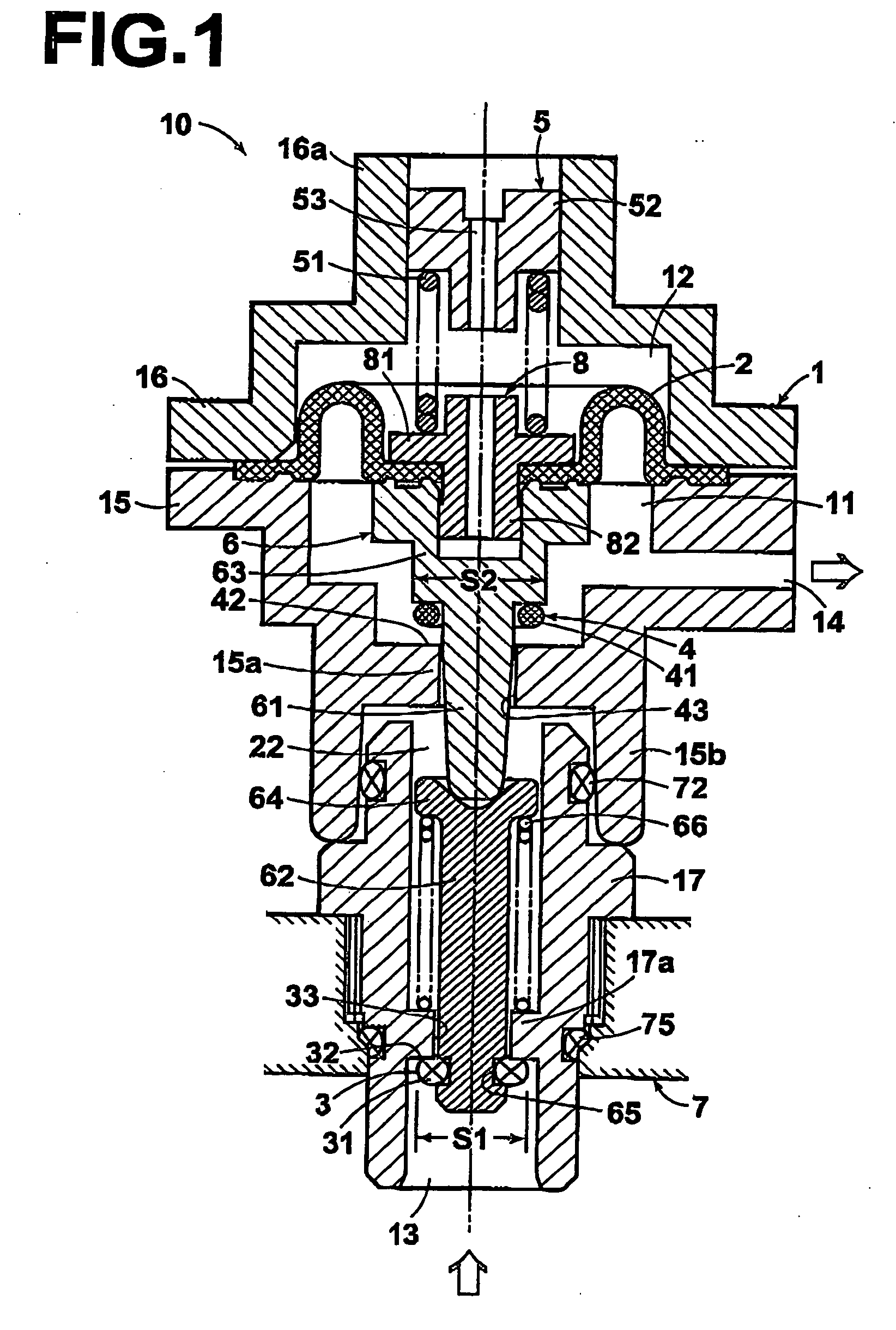
[0023] According to the invention as described above, the shaft that is operated by a diaphragm that is displaced in response to a secondary pressure comprises: a primary regulating valve for reducing a primary pressure to the secondary pressure; and a secondary regulating valve that is operatively associated with the primary regulating valve so as to further regulate a fluid passed through the primary regulating valve by opening-closing operations in reverse to those of the primary regulating valve, as a result of which the pressure regulation characteristic of the secondary regulating valve against the fluctuations in the primary pressure is reverse to the pressure regulation characteristic of the primary regulating valve. By combining these two valves having the pressure regulation characteristics reverse to each other, the primary pressure can be more accurately reduced and regulated to the secondary pressure, and a situation that the secondary pressure becomes zero is avoided even during the regulation to the secondary pressure which is low, and a constant secondary pressure can be maintained with a simpler structure.
[0024] When the pressure loss that a projected area of the primary regulating valve undergoes and the pressure loss that a projected area of the secondary regulating valve undergoes are provided such that they act in the same direction, the pressure regulation characteristics of these valves which are reverse to each other can be easily ensured while simplifying the mechanism.
[0025] Still further, when the primary regulating valve and the secondary regulating valve are disposed such that they respectively act in directions which are different from each other, good pressure regulation characteristics can be obtained even when the dimensional accuracy regarding the positional relationship between these regulating valves is not so strict. This facilitates the manufacture of the pressure regulator.
[0026] In addition, the secondary regulating valve in a non-operating state also serves as a check valve, which prevents backflow of the fluid and therefore avoids effects of fluid leaks to a system in which the pressure regulator is incorporated. Thus, the pressure regulator of the present invention is suitable for practical application.
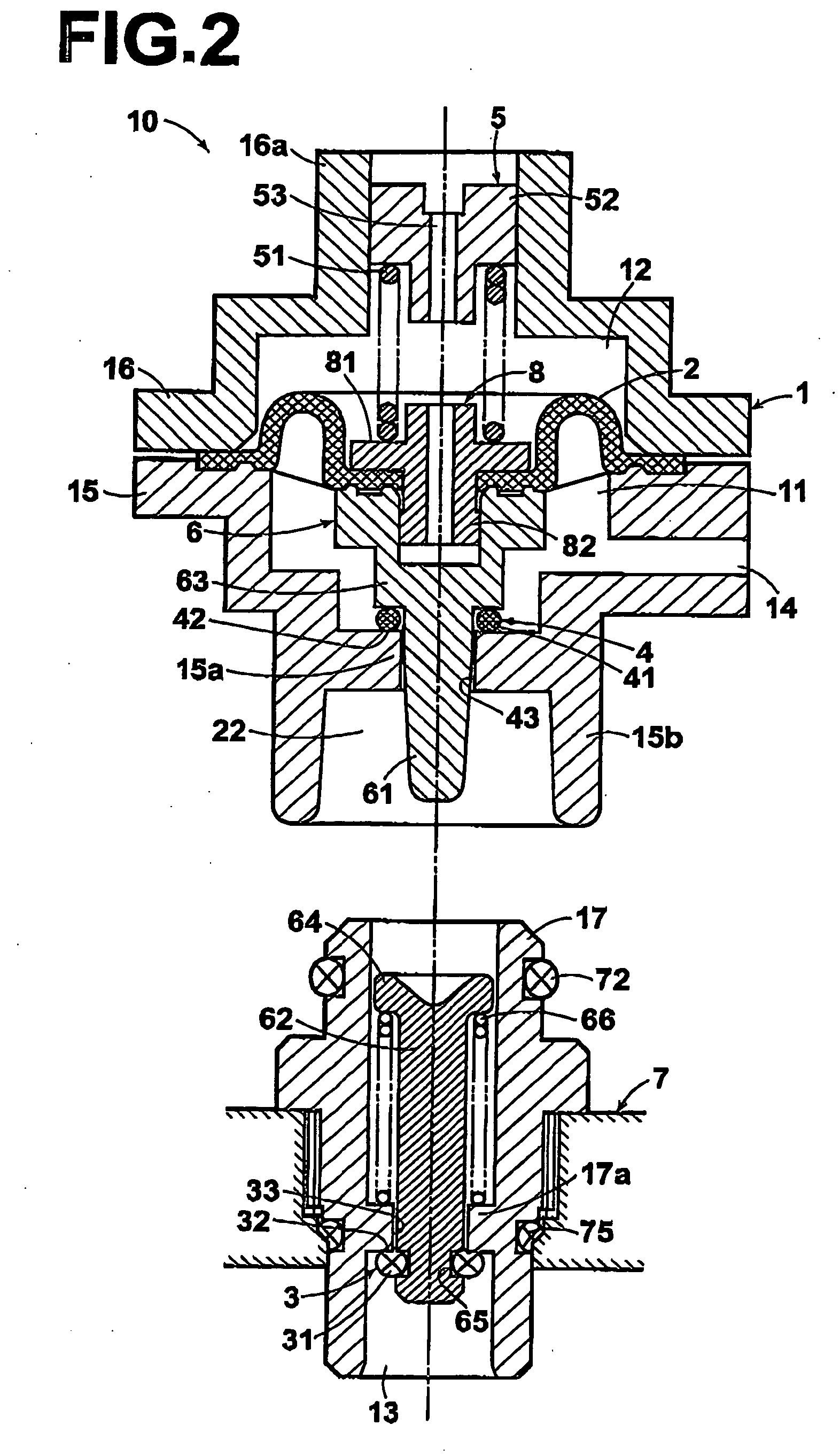
[0027] Particularly, when the shaft is divided into the first shaft section for holding the primary regulating valve and the second shaft section for holding the secondary regulating valve so that the casing is divided between these shaft sections so as to be removable, the pressure vessel containing therein a fluid can be easily removed from the pressure regulator and replaced with new one. Thus, such a configuration is suitable for use in a fuel supply system for fuel cells.
[0028] On the other hand, when the primary regulating valve and the secondary regulating valve are disposed on the shaft so as to be separated from each other leaving a predetermined space therebetween and are operatively associated with each other such that the valves open and close a single aperture in a reverse relationship to each other on either side of the aperture, the pressure regulator can be made compact.

Problems solved by technology

However, in the duplex-valve type pressure regulator, it is difficult to appropriately position the two regulating valves 306 and 307.
In practice, for the single-valve type pressure regulator having a simple diaphragm and a regulating valve, however, the pressure loss at the regulating valve causes decreases of the secondary pressure with increases of the primary pressure as described above, and accordingly it is difficult to accurately provide a target secondary pressure with respect to a wide primary pressure range.
On the other hand, for the duplex-valve type pressure regulator having a subsidiary regulating valve for canceling the pressure lose that the regulator undergoes, the body structure is large and complex compared with the single-valve type pressure regulator.
Further, in the duplex-valve type pressure regulator, positioning of these two valves is difficult since a precise alignment of the valves to one another is required.
Thus, the duplex-valve type pressure regulator is superior in operating principles, but not adequate for practical applications.

Method used


Image

  • Pressure regulator
  • Pressure regulator
  • Pressure regulator

Examples


example 1

MEASUREMENT EXAMPLE 1

[0091] In Measurement Example 1, fluctuations in the secondary pressure P2 were measured while changing a primary pressure P1 of a fluid supplied to a pressure regulator 10 when the secondary pressure P2 was set relatively high. The results of the measurement are shown in FIG. 8 where a solid line indicates the results of the measurement on the pressure regulator of the present invention, while a broken line indicates the results of the measurement on a comparative example.

[0092] Setting parameters used in this measurement were as follows; set secondary pressure P25 kPa; effective area 123 mm2 (dia. 12.5 mm); projection area of primary regulating valve 5 mm2 (dia. 2.5 mm); projection area of secondary regulating valve 7 mm2 (dia. 3.0 mm); spring constant of pressure regulating spring 0.5 N / mm; wire diameter of pressure regulating spring 0.35 mm; outer diameter of pressure regulating spring 3.0 mm; total length of pressure regulating spring 15.0 mm; set length o...

example 2

MEASUREMENT EXAMPLE 2

[0096] In Measurement Example 2, fluctuations in the secondary pressure P2 were measured while changing a primary pressure P1 of a fluid supplied to a pressure regulator 10 when the secondary pressure P2 was set relatively low. The results of the measurement are shown in FIG. 9 where a solid line indicates the results of the measurement on the pressure regulator of the present invention. The regulated pressure of the comparative example was unstable and could not be measured.

[0097] Setting parameters used in this measurement were as follows: set secondary pressure 7 kPa; effective area of diaphragm 123 mm2 (dia. 12.5 mm); projection area of primary regulating valve 5 mm2 (dia. 2.5 mm); projection area of secondary regulating valve 7 mm2 (dia. 3.0 mm); spring constant of pressure regulating spring 0.27 N / mm; wire diameter of pressure regulating spring 0.3 mm; outer diameter of pressure regulating spring 3.0 mm; total length of pressure regulating spring 15.0 mm;...


PUM


Abstract

A pressure regulator include a fluid introducing port; a primary regulating valve for reducing the primary pressure to a secondary pressure; a pressure regulating chamber receiving the fluid from the first pressure regulating valve; a diaphragm which is being displaced in response to the secondary pressure; a shift for drivingly connecting the diaphragm and the primary regulating valve; a pressure-setting section for adjusting a displacement magnitude of the diaphragm; and a discharging port through which the fluid of secondary pressure is discharged. The shaft includes a secondary regulating valve operatively associated with the primary regulating valve so as to further regulate the fluid from the primary regulating valve by opening-closing operations in reverse to those of the primary regulating valve. Hence, the pressure regulation characteristic of the secondary regulating valve against the fluctuations in the primary pressure become reverse to that of the primary regulating valve.

Description

BACKGROUND OF THE INVENTION [0001] 1. Field of the Invention [0002] The present invention relates to a pressure regulator for reducing a primary pressure to a constant secondary pressure, and more specifically relates to a pressure regulator having a feature suitable for use for ensuring a stable fuel supply over an extended period, for example, when supplying a fuel cell with a low pressure liquid fuel or a gaseous fuel. [0003] 2. Description of the Related Art [0004] Conventionally, pressure regulators, also referred to as pressure governors, for reducing the pressures of the high-pressure gases have been utilized widely in liquefied gas utilizing appliances, gas supply facilities, and the like. The pressure regulator includes a diaphragm for detecting a secondary pressure; and a pressure-regulating valve movable in association with the displacement of the diaphragm, and is structured such that the pressure-regulating valve is operated to keep the secondary pressure constant even ...

Claims


Application Information

Patent Timeline
IPC IPC(8): G05D16/06
CPCG05D16/0666G05D16/0658Y10T137/7826
Inventor NAKAMURA, YASUAKI
Owner TOKAI
Learn More