Printhead substrate, printhead, head cartridge, and printing apparatus

a printing apparatus and printhead technology, applied in printing and other directions, can solve the problems of unstable ink discharge, limited current value which can be supplied at once, and increase the resistance of wiring resistance and variations, so as to achieve stable printing, shorten the wiring length from the signal input pad to the constant electric current source, and use

Inactive Publication Date: 2005-12-01
CANON KK
View PDF9 Cites 52 Cited by
  • Summary
  • Abstract
  • Description
  • Claims
  • Application Information

AI Technical Summary

Benefits of technology

[0026] For example, a printhead substrate, a printhead integrating the printhead substrate, a head cartridge integrating the printhead, and a printing apparatus using the printhead according to the present invention are capable of downsizing the size, driving a printing element at a high speed while adopting a constant current driving method of supplying a constant current to each printing element to drive it.
[0041] The invention is particularly advantageous since a plurality of printing elements and a plurality of switching elements which are very large in number are arrayed in the longitudinal direction of a board, a pad which receives a driving signal and a control signal that are used to drive the plurality of printing elements is arranged at the end of the board in the widthwise direction of the board, and a constant electric current source for supplying a constant electric current is interposed between these two regions. The board area can be effectively utilized, and the wiring length from the signal input pad to the constant electric current source can be shortened on the board. Hence, the present invention can provide a head substrate capable of stable printing at a high speed without increasing the size of the head substrate.

Problems solved by technology

However, due to the limited capacity of the power supply of a printing apparatus having the printhead and a voltage drop caused by the resistance of a wiring line extending from the power supply to the heater, a current value which can be supplied at once is limited.
This problem occurs also when the head substrate is downsized, and the wiring resistance and variations in resistance increase.
When energy applied to a heater is too small, ink discharge becomes unstable; when the energy is too large, the heater durability degrades.
In other words, in a case where the variation of the voltage applied to heaters is large, the heater durability degrades or ink discharge becomes unstable.
However, as the number of concurrently driven heaters increases, a current flowing through a common wiring line generates a large amount of voltage drop.
The voltage application time in heater driving must be prolonged to compensate for the voltage drop, and this makes it difficult to drive a heater at a high speed.
As a result, the area of the heater substrate becomes much larger than that in a conventional driving method, and the cost of the heater substrate becomes higher.
It is difficult to reduce variations in output current between a plurality of constant current sources particularly on a head substrate having a greater number of heaters for higher speed and higher precision of printing in the printing apparatus.

Method used


Image

  • Printhead substrate, printhead, head cartridge, and printing apparatus
  • Printhead substrate, printhead, head cartridge, and printing apparatus
  • Printhead substrate, printhead, head cartridge, and printing apparatus

Examples


first embodiment

[0118]FIG. 8 is a view showing the layout of a head substrate according to the first embodiment of the present invention.

[0119]FIG. 8 is an example of a layout for illustrating an actual arrangement of elements, such as the heaters, transistors, control circuits, and constant electric current sources, in the heater driving circuit (equivalent circuit) shown in FIG. 5. Also in FIG. 8, the same reference numerals as those in FIG. 5 denote areas where the corresponding building components are arranged. Note that the head substrate according to the present invention is a rectangular substrate with longer sides and shorter sides. Heaters and transistors for switching are arrayed along with the longer side direction (longitudinal direction).

[0120] For example, in a group 1100-1, a heater group and transistor group respectively including heaters 1101-11 to 1101-1x and MOS transistors 1102-11 to 1102-1x are formed. In a group 1100-2, a heater group and transistor group respectively includ...

second embodiment

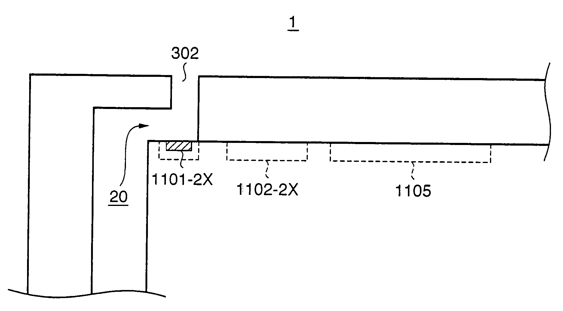
[0134]FIG. 11 is a view showing the layout of a head substrate according to the second embodiment of the present invention.

[0135]FIG. 11 illustrates an example of a layout which implements the heater driving circuit shown in FIG. 5. Chain lines shown in FIG. 11 represent symmetric axes. Also in FIG. 11, the same reference numerals as those in FIG. 5 denote the same building components.

[0136]FIG. 12 is a view showing the layout of power supply lines on the head substrate shown in FIG. 11.

[0137] In the layout of the second embodiment, four heater driving circuits shown in FIG. 5 are symmetrically arranged on the same head substrate. The operation of each circuit is the same as that described in the first embodiment. Hence, reference numerals are given to only one of the four sections. In this arrangement, ink is supplied from a hole (ink channels 2C, 2M, 2Y) at the center of the substrate to heaters arranged on the upper surface of the head substrate, as shown in FIG. 3. By supplyi...

third embodiment

[0141]FIG. 13 is a circuit block diagram showing the arrangement of the head substrate of a printhead IJH which adopts a constant electric current driving method according to the third embodiment. Also in FIG. 13, the same reference numerals as those described above denote the same building components. In FIG. 13, reference numerals 1102-11 to 1102-mx denote switches, and their entities are MOS transistors which function as switching elements, as described above.

[0142] The circuit arrangement is mainly comprised of a reference voltage circuit 101, a voltage-to-current conversion circuit 102, a reference current circuit 103, and n constant electric current source groups (heater driving circuits) 106-1 to 106-n.

[0143] The arrangement shown in FIG. 13 can supply an electric current to n constant electric current source groups (heater driving circuits). The (x×m) heaters in each group may be made to correspond to n nozzle arrays for discharging ink of the same color or n nozzle arrays...


PUM


Abstract

An object of this invention is to provide a driving circuit layout which suppresses an increase in the area of a head substrate in an inkjet printhead adopting a constant electric current driving method. To achieve this object, a plurality of printing elements and a plurality of switching elements which are very large in number are arrayed in the longitudinal direction of a head substrate. A terminal which receives a driving signal and a control signal that are used to drive the plurality of printing elements is arranged at the end of the board in the widthwise direction of the board. A electric current source for supplying a predetermined electric current is interposed in an area between these two areas.

Description

FIELD OF THE INVENTION [0001] This invention relates to a printhead substrate, printhead, head cartridge, and printing apparatus and, more particularly, to a printhead substrate, containing a circuit for driving a printing element by sending a predetermined electric current, which is used to print in accordance with an inkjet method, printhead, head cartridge, and printing apparatus. BACKGROUND OF THE INVENTION [0002] An inkjet printhead (to be referred to as a printhead hereinafter), which generates thermal energy by sending an electric current to a heater arranged in the nozzle so as to discharges ink, has conventionally been known. [0003] This printhead is a printhead which employs a method of bubbling ink near the heater by using the generated thermal energy, and discharging ink from the nozzle to print. [0004] In order to print at a high speed, heaters (printing elements) mounted in a printhead are desirably concurrently driven as many as possible to discharge ink at the same t...

Claims


Application Information

Patent Timeline
Patent Type & Authority Applications(United States)
IPC IPC(8): B41J2/04B41J2/05B41J2/14
CPCB41J2/04541B41J2/04543B41J2/04545B41J2/0455B41J2/14072B41J2/0457B41J2/0458B41J2/04588B41J2/0459B41J2/04568B41J2/04501B41J2/05
Inventor HIRAYAMA, NOBUYUKI
Owner CANON KK
Why Eureka
Try Eureka