Image pickup apparatus for capturing spectral images of an object and observation system including the same

a technology of spectral images and pickup apparatus, which is applied in the field of image pickup apparatus for obtaining spectral images of objects, can solve the problems of inability to provide color object images, and inability to obtain small-wavelength separation bands using a rotating filter or variable transmittance elemen

Active Publication Date: 2005-12-01
OLYMPUS CORP
View PDF8 Cites 18 Cited by
  • Summary
  • Abstract
  • Description
  • Claims
  • Application Information

AI Technical Summary

Benefits of technology

[0010] The present invention provides a small image pickup apparatus that simultaneou...

Problems solved by technology

However, it is difficult to obtain bands of smaller-wavelength separations using a rotating filter or a variable transmittance element.
Therefore, high-resolution extraction of the spectrum of the object from obtained spectral images cannot be achieved.
However, these devices do not provide color object images, making it impossible to examine the object while obtaining spectral information or to identify from which part of the...

Method used


Image

  • Image pickup apparatus for capturing spectral images of an object and observation system including the same
  • Image pickup apparatus for capturing spectral images of an object and observation system including the same
  • Image pickup apparatus for capturing spectral images of an object and observation system including the same

Examples


embodiment 1

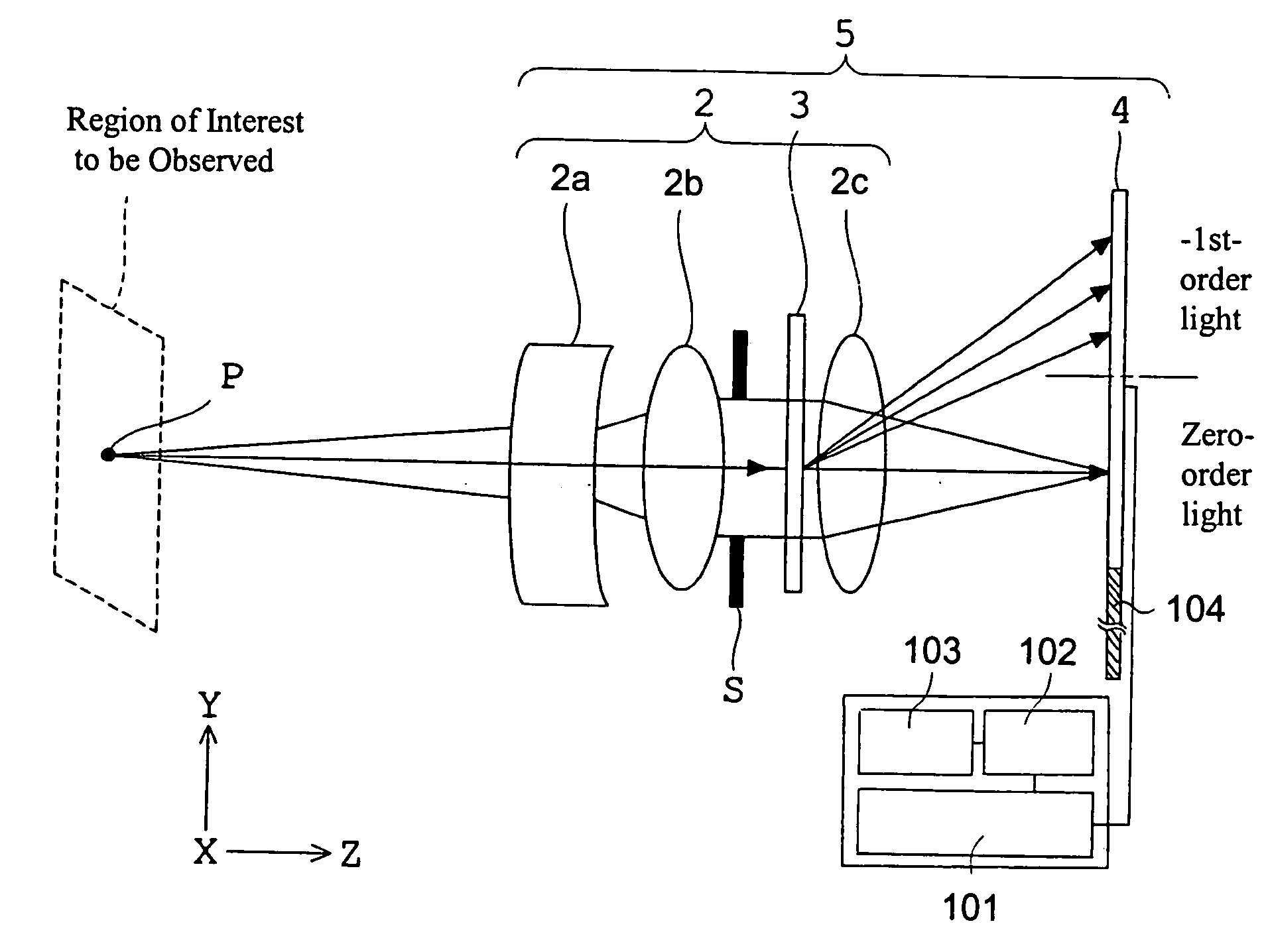
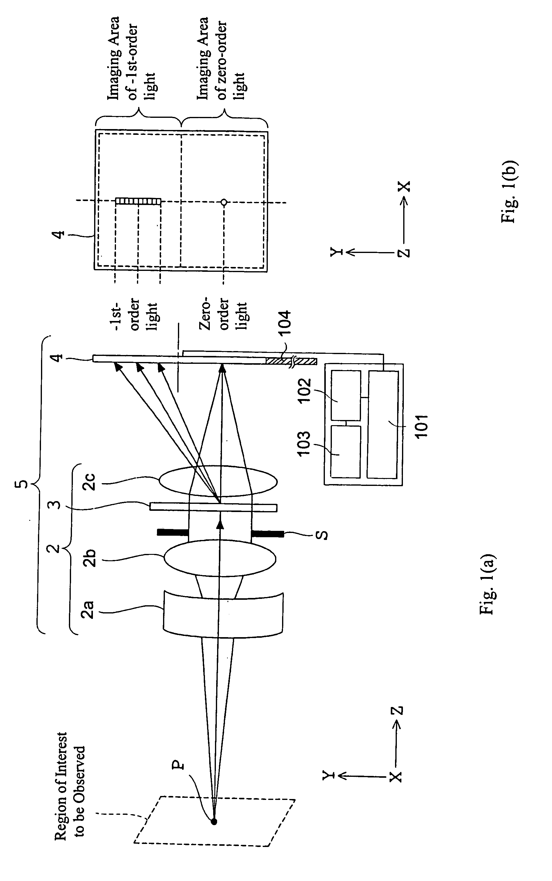
[0032] The construction of an image pickup apparatus according to Embodiment 1 of the present invention will now be described with reference to FIGS. 1(a) and 1(b). FIG. 1(a) is a cross-section containing the optical axis of the observation optical system that shows the basic construction of an image pickup apparatus 5, and FIG. 1(b) is a view along the optical axis that shows the imaging areas of −1st-order light and zero-order light on the image pickup surface of a solid-state image pickup element. The image pickup apparatus 5 of the present invention is formed of an observation optical system 2 that includes a diffraction element 3 located in the optical path, and a solid-state image pickup element 4. The observation optical system 2 includes a lens 2a provided on the object surface side, and a collimating lens 2b for collimating a light flux from the lens 2a. In addition, the observation optical system 2 includes a diaphragm S and the diffraction element 3, each of which is loca...

embodiment 2

[0068] The construction of an image pickup apparatus according to Embodiment 2 of the present invention will now be described with reference to FIGS. 4(a) and 4(b). FIG. 4(a) is a cross-section containing the optical axis of the observation optical system showing the basic construction of the image pickup apparatus 5. FIG. 4(b) is an illustration showing the imaging areas of the −1 st-order light and zero-order light on the image pickup surface of a solid-state image pickup element 4, as viewed from a position on the optical axis facing the image pickup surface.

[0069] The image pickup apparatus 5 of Embodiment 2 of the present invention is formed of an observation optical system 2 which may include a diffraction element 3 located in the optical path, and a solid-state image pickup element 4. The observation optical system 2 is formed of a lens 2a located on the object surface side of the observation optical system 2, a collimating lens 2b for collimating a light beam from the lens ...

embodiment 3

[0077] The construction of an image pickup apparatus according to Embodiment 3 of the present invention will now be described with reference to FIGS. 8(a) and 8(b). FIG. 8(a) is a cross-section containing the optical axis of the observation optical system that shows the basic construction of an image pickup apparatus 5, and FIG. 8(b) is a view in the direction of the optical axis that shows the imaging areas of −1st-order light and zero-order light on the image pickup surface of a solid-state image pickup element 4.

[0078] The image pickup apparatus 5 of this embodiment is formed of an observation optical system 2 which includes a diffraction element 3 located in the optical path, and a solid-state image pickup element 4. The observation optical system 2 is formed of a lens 2a on the object surface side of the observation optical system, a collimating lens 2b for collimating a light flux from the lens 2a, a diaphragm S and a diffraction element 3 provided in the collimated light flu...


PUM


Abstract

An image pickup apparatus has a construction in which a diffraction element is provided in an observation optical system. Zero-order light that is transmitted straight through the diffraction element and one of the +1st-order diffracted light and the −1st-order diffracted light that is diffracted by the diffraction element are imaged onto an image pickup surface of an image pickup apparatus. The imaging areas of the zero-order light and one of the +1st-order diffracted light and the −1st-order diffracted light that is diffracted by the diffraction element do not overlap on the image pickup surface of the image pickup apparatus. With this construction, a small image pickup apparatus that provides a high-resolution spectral image and a color image of an object can be obtained.

Description

[0001] This application claims benefit under 35 U.S.C. §119 of JP 2004-154659, filed May 25, 2004, the contents of which are hereby incorporated by reference. BACKGROUND OF THE INVENTION [0002] The present invention relates to an image pickup apparatus for obtaining spectral images of an object, and particularly relates to an image pickup unit in a medical endoscope for obtaining spectral images of fluorescence emitted by living tissue, and an analysis device for analyzing obtained spectral images, such as measuring fluorescent wavelengths for living tissue diagnosis, and is also concerned with an image pickup unit in an industrial inspection device for obtaining spectral images of luminous surfaces such as those of LEDs and an analysis device for analyzing obtained spectral images, such as measuring spectroscopic properties of an object surface for quality control on a production line. [0003] Devices in the prior art for measuring spectroscopic properties include those described in...

Claims


Application Information

Patent Timeline
IPC IPC(8): G01J3/18A61B1/06G01J3/02G01J3/28G01J3/30G01J3/36G01J3/443G01M11/00G01N21/31G01N21/49G02B23/24G02B27/10H04N5/225
CPCG01J3/02G01J3/0264G01J3/2823G01J3/30G01J3/36G01N21/31G02B27/145G01N2021/1793G01N2021/3137G01N2021/317G02B23/2423G02B27/1086G02B27/144G01N21/49
Inventor TAKAHASHI, SUSUMU
Owner OLYMPUS CORP
Why Eureka
Try Eureka