Bearing assembly with anti-slip spring

a technology of anti-slip springs and bearings, applied in the direction of elastic bearings, rigid support of bearing units, mechanical apparatus, etc., can solve the problems of micro-mechanical relative movements, increased stress concentration, pitting and galling of contact surfaces, etc., to reduce fretting and bearing creep, easy assembly, and prolong usable life

Inactive Publication Date: 2005-12-01
NIDEC MOTOR CORP
View PDF11 Cites 14 Cited by
  • Summary
  • Abstract
  • Description
  • Claims
  • Application Information

AI Technical Summary

Benefits of technology

[0006] Among the several objects and features of exemplary embodiments of the present invention may be noted the provision of a bearing system which extends usable life; the provision of an exemplary bearing system which reduces fretting and bearing creep; the provision of an exemplary bearing system usable in an electric motor; the provision of an exemplary bearing system which is easily assembled; the provision of an exemplary bearing system which is reliable in operation; the provision of an exemplary bearing system which inhibits vibration and reduces noise levels; and the provision of an exemplary bearing system which is economical to produce.

Problems solved by technology

A substantial concern in machinery is fretting, which results from slight, micro-mechanical relative movements between tightly fitting parts which superficially appear immobile with respect to each other.
If it continues, fretting can result in pitting and galling of contact surfaces, vibration, increased stress concentrations, and reduced life.
In an electric motor, fretting is a primary cause of bearing failure.
Unfortunately, the outer surface of the bearing is subject to rotate relative to the bore in which it is received.
Even a bearing which is sized for a tight fit tends to become loose when ambient temperature varies because of differential thermal expansions between the bearing and endshield.
As a result, slight relative movements occur between outer bearing surface and bore, which produce fretting damage.
Unfortunately, the washer does not provide significant resistance to rotation of the bearing.
First, the contour of the washer provides only a small area of contact between the washer and the end face of the bearing, specifically at the three high points.
Second, surface adhesion (i.e., friction coefficient) at the area of contact is relatively low because the materials in contact are both metallic.
As fretting continues, the bearing eventually moves in a radial direction, known to those skilled in the art as bearing creep, which causes the rotor to strike the stator.
Several previous approaches for preventing rotation of the bearing have failed or required an additional insert or adhesive along the outer sides of the bearing, which increases complexity, degrades reliability, or makes assembly more difficult.

Method used


Image

  • Bearing assembly with anti-slip spring
  • Bearing assembly with anti-slip spring
  • Bearing assembly with anti-slip spring

Examples


Embodiment Construction

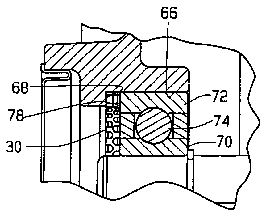
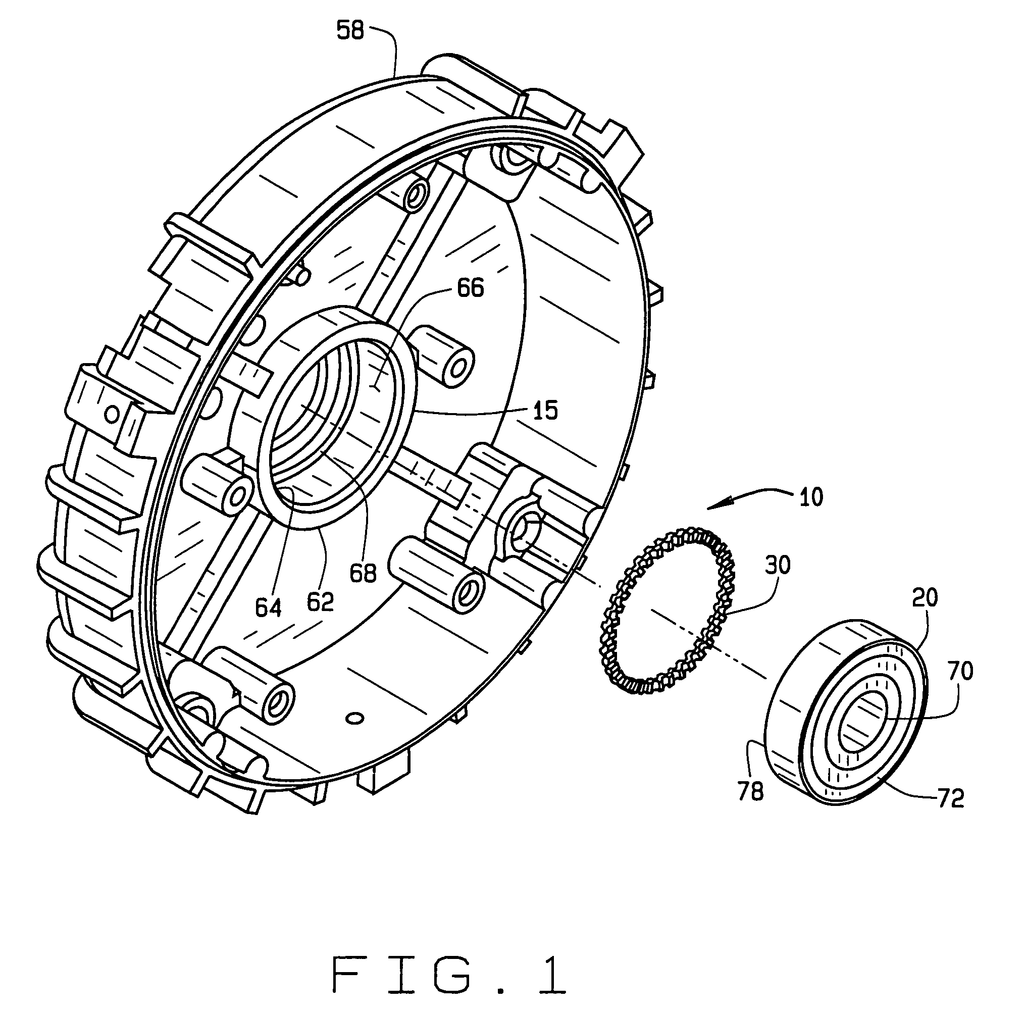
[0017] Referring now to the drawings and in particular to FIG. 1, a bearing system according to one embodiment of the present invention is indicated generally at 10. The bearing system 10 includes a bearing housing 15, a bearing 20 receivable in the housing, and an anti-slip spring member 30 which inhibits rotation of the bearing in the housing and reduces damage due to fretting. In one embodiment, the bearing system 10 is intended for installation in a dynamoelectric machine, such as an electric motor 40 (FIG. 5) or a generator. Although the description herein is primarily with reference to that embodiment, it is understood that the bearing system has wide application and may be used with other devices, machinery, or equipment in other fields of industry without departing from the scope of this invention.

[0018] Referring to FIG. 5, the electric motor 40 includes a casing 42 having a hollow interior. A stationary assembly or stator (generally designated 44) and a rotatable assembly...


PUM


Abstract

A bearing system which inhibits fretting to extend the life of a bearing. The system is usable in a machine, such as an electric motor, and includes an elastomeric spring positioned between the bearing and a bottom surface of a bore in which the bearing is received. The spring member applies force to the bearing in both an axial direction and a circumferential direction to oppose rotation of the bearing in the bore. The spring member has an annular shape with a plurality of circumferentially spaced teeth.

Description

BACKGROUND OF THE INVENTION [0001] This invention relates generally to rolling bearings, and in particular to an elastomeric spring for a bearing assembly in an electric motor which inhibits fretting damage and extends the life of the bearing. [0002] A substantial concern in machinery is fretting, which results from slight, micro-mechanical relative movements between tightly fitting parts which superficially appear immobile with respect to each other. Fretting is a combination of corrosion and abrasion which is frequently observed on equipment with moving or vibrating parts. If it continues, fretting can result in pitting and galling of contact surfaces, vibration, increased stress concentrations, and reduced life. [0003] In an electric motor, fretting is a primary cause of bearing failure. As known to those skilled in the art, a motor has a rotatable assembly, or rotor, mounted within a hollow core of a stationary assembly, or stator, which holds windings of insulated wire. The mot...

Claims


Application Information

Patent Timeline
Patent Type & Authority Applications(United States)
IPC IPC(8): F16C25/08F16C27/06F16C35/067F16C35/077H02K5/173
CPCF16C25/08F16C27/066Y10S384/906H02K5/1732F16C35/077F16C19/06F16C25/083F16C35/067F16C2226/10F16C2380/26
Inventor JONES, PATRICK M.
Owner NIDEC MOTOR CORP
Why Eureka
Try Eureka