Utilization-based fuel cell monitoring and control

a fuel cell and utilization-based technology, applied in the field of utilization-based fuel cell monitoring and control, can solve the problems of increasing increasing and increasing the consumption of fuel, so as to increase the production of electric current and fuel consumption, increase the fuel utilization rate, and increase the applied load

Active Publication Date: 2005-12-01
DCNS SA
View PDF99 Cites 17 Cited by
  • Summary
  • Abstract
  • Description
  • Claims
  • Application Information

AI Technical Summary

Benefits of technology

[0007] In some energy producing and consuming assemblies, the fuel utilization rate, or amount of fuel consumed per amount supplied, may be a function of the supply fuel feed rate and the load applied to the fuel cell stack. For example, for a fixed supply fuel feed rate, an increased applied load will increase the production of electric current and the fuel consumption, thereby increasing the fuel utilization rate. Similarly, a decreased applied load will decrease the production of electric current and decrease fuel consumption, thereby decreasing the fuel utilization rate.
[0008] In some assemblies, there is a predetermined maximum fuel utilization rate to prevent contamination of or other damage to the energy producing and consuming assemblies. Additionally, there may be a predetermined minimum fuel utilization rate to prevent excessive waste of the supply fuel. Controlling the fuel utilization rates by actively controlling the applied load may allow for improved responsiveness and greater control over the utilization rate. Actively controlling the applied load together with active control of the fuel source, based on the flow of unused fuel, may allow greater control of the fuel utilization rate over a wide range of operating conditions.

Problems solved by technology

For example, for a fixed supply fuel feed rate, an increased applied load will increase the production of electric current and the fuel consumption, thereby increasing the fuel utilization rate.
Similarly, a decreased applied load will decrease the production of electric current and decrease fuel consumption, thereby decreasing the fuel utilization rate.

Method used


Image

  • Utilization-based fuel cell monitoring and control
  • Utilization-based fuel cell monitoring and control
  • Utilization-based fuel cell monitoring and control

Examples


Embodiment Construction

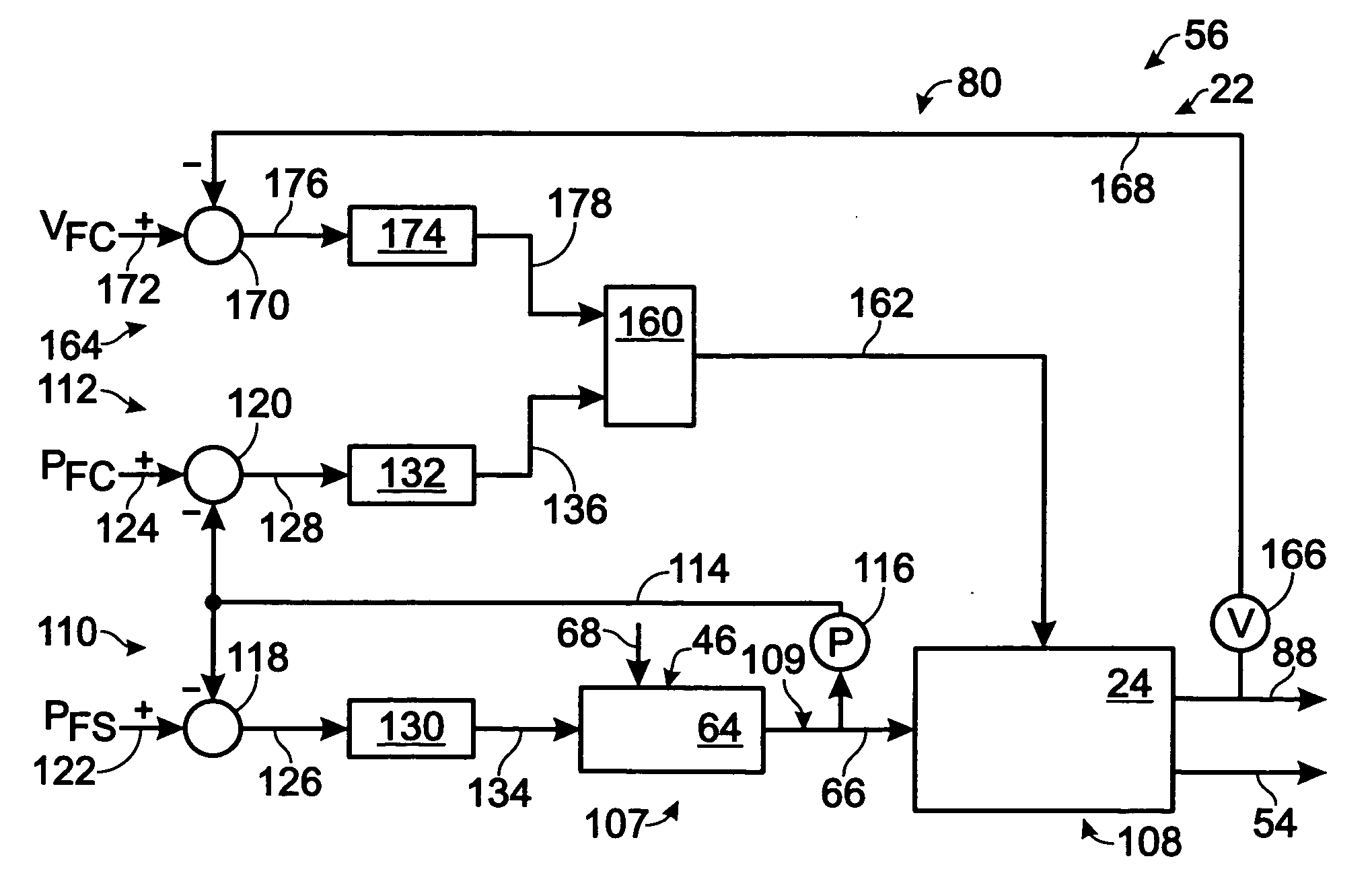
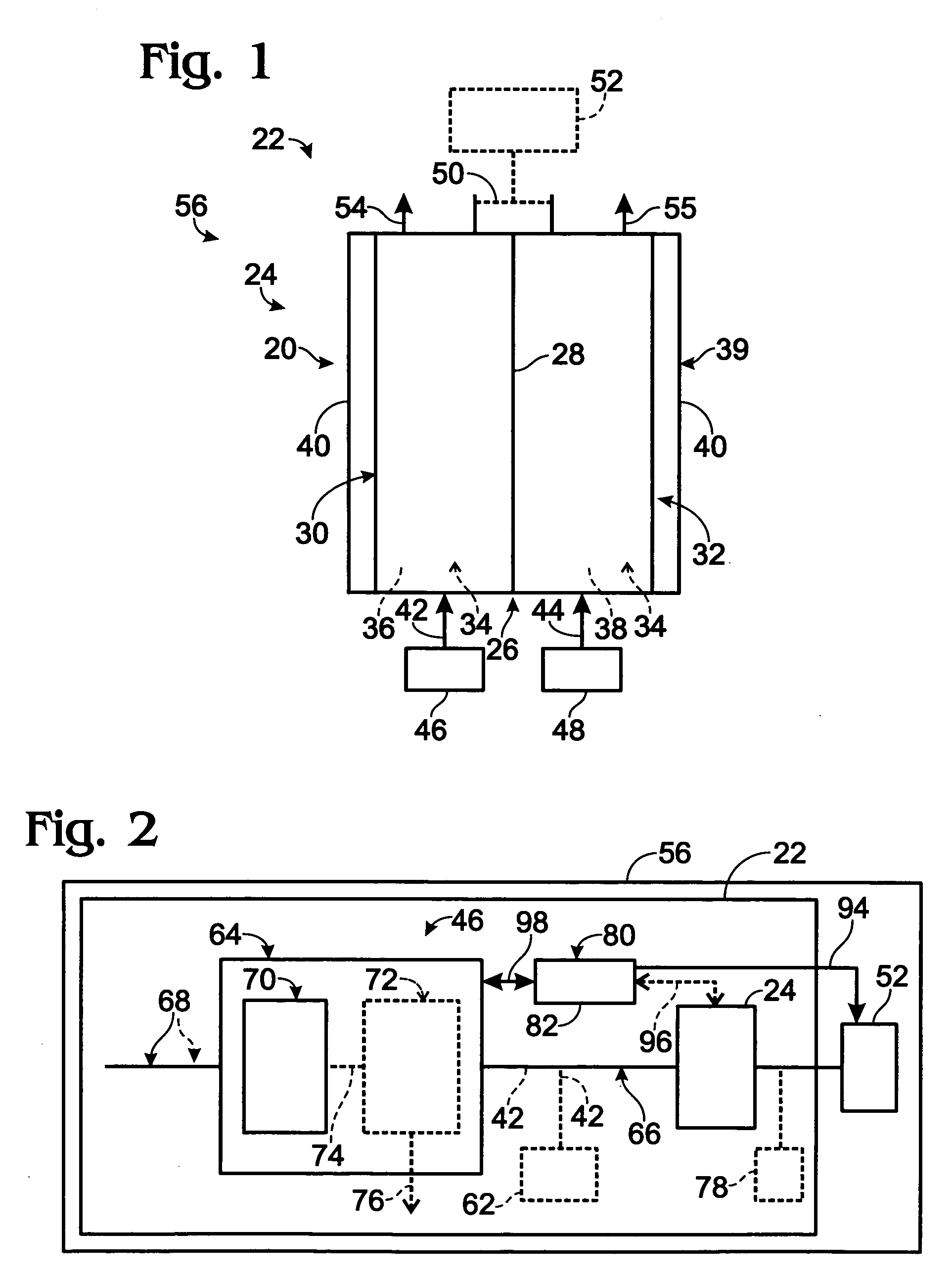
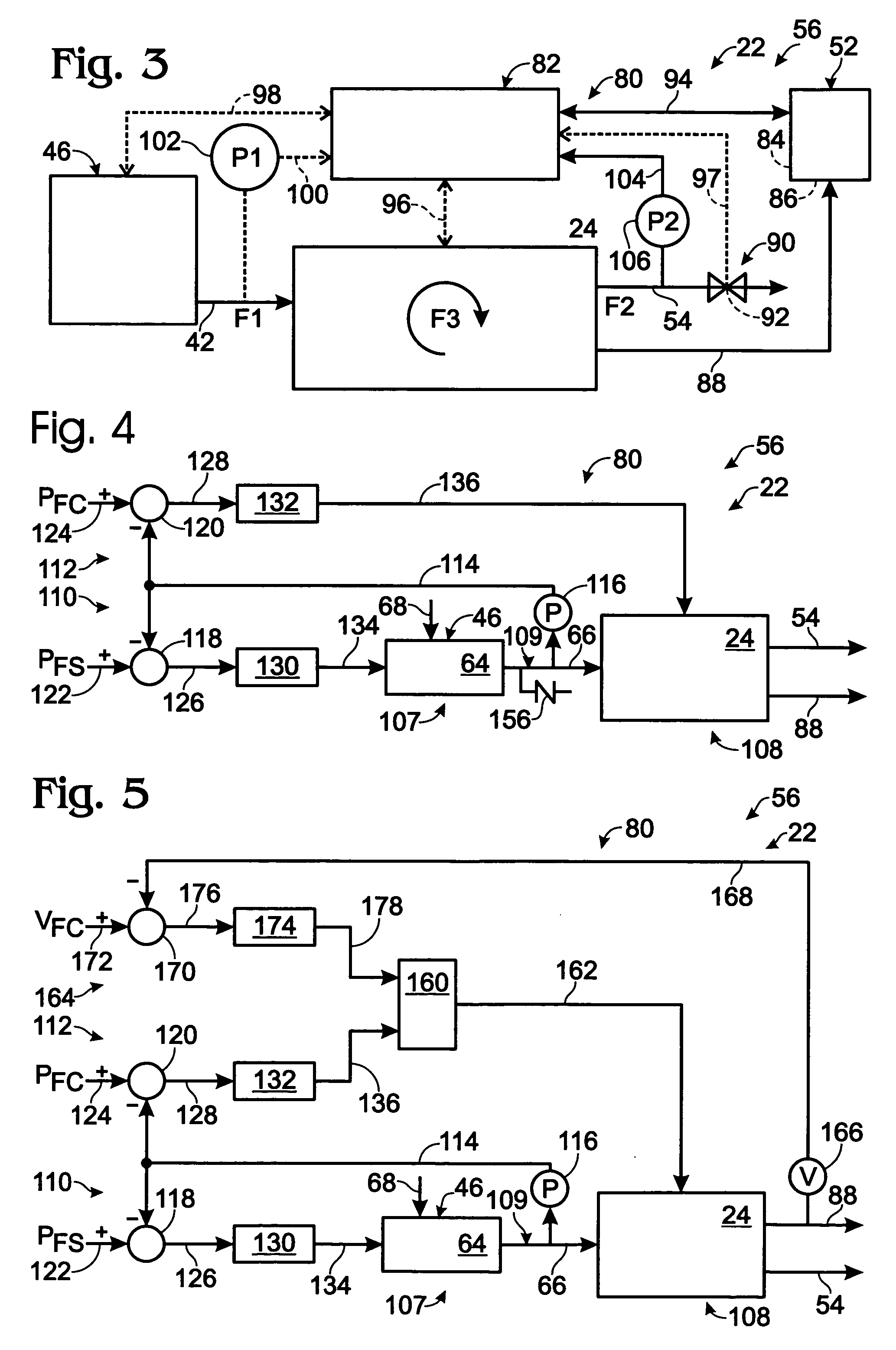
[0019] As has been mentioned, methods and systems are disclosed for controlling the operation of a fuel cell stack. As used herein, a fuel cell stack includes one or more fuel cells, whether individually or in groups of fuel cells, and typically includes a plurality of fuel cells coupled between common end plates. A fuel cell system includes one or more fuel cell stacks and at least one fuel source for the fuel cell stack(s). Additionally, an energy producing and consuming assembly includes one or more fuel cell stacks, at least one fuel source for the fuel cell stack(s), and at least one energy-storing / consuming assembly adapted to exert an applied load on the fuel cell stack.

[0020] The subsequently discussed fuel cell stacks and systems are compatible with a variety of different types of fuel cells, such as proton exchange membrane (PEM) fuel cells, alkaline fuel cells, solid oxide fuel cells, molten carbonate fuel cells, phosphoric acid fuel cells, and the like. For the purpose ...


PUM

PropertyMeasurementUnit
thickaaaaaaaaaa
pressuresaaaaaaaaaa
pressuresaaaaaaaaaa

Abstract

Fuel cell systems and methods for controlling the operation of components of the fuel cell system, which may include a fuel source and a fuel cell stack. In some examples, a fuel source is adapted to provide supply fuel to a fuel cell stack at a supply pressure. The fuel cell stack produces electric current at a production amperage. In some examples, a control system is adapted to control operation of the fuel cell stack based on a pressure detected at the fuel cell stack. In some examples, a target production amperage is determined based on the detected pressure, such that when electric current is produced at the target production amperage for the detected pressure, the fuel cell stack consumes a predetermined proportion of the supply fuel.

Description

RELATED APPLICATIONS [0001] This application is a continuation-in-part of and claims priority to U.S. patent application Ser. No. 10 / 857,629, which was filed on May 28, 2004 and is entitled Consumption-based Fuel Cell Monitoring and Control.” This application is also a continuation-in-part of and claims priority to U.S. patent application Ser. No. 10 / 909,266, which was filed on Jul. 29, 2004, and is entitled “Shared Variable-based Fuel Cell System Control.” The complete disclosures of the above-identified patent applications are hereby incorporated by reference for all purposes.TECHNICAL FIELD [0002] The present disclosure relates generally to fuel cell systems, and more particularly to systems and methods for determining and controlling one or more variables in a fuel cell system. BACKGROUND OF THE DISCLOSURE [0003] An electrochemical fuel cell is a device that converts fuel and an oxidant to electricity, a reaction product, and heat. For example, fuel cells may be adapted to conve...

Claims


Application Information

Patent Timeline
Patent Type & Authority Applications(United States)
IPC IPC(8): H01M50/77
CPCH01M8/04089H01M8/04402H01M8/04589Y02E60/50H01M8/0612H01M8/0662H01M8/04753Y02P70/50
Inventor EDLUND, DAVID J.LAVEN, ARNESCHARF, MESA
Owner DCNS SA
Why Eureka
Try Eureka