Systems, devices and apparatuses for bony fixation and disk repair and replacement and methods related thereto

Inactive Publication Date: 2005-12-01
K2M
View PDF5 Cites 152 Cited by
  • Summary
  • Abstract
  • Description
  • Claims
  • Application Information

AI Technical Summary

Benefits of technology

[0015] The present invention features new methods, apparatuses and devices for fixing adjacent bone segments, segments of a bony structure and adjacent vertebrate of a spine. The methods, apparatuses and devices utilize a new apparatus for forming a channel in a surface of the bone or bony structure segments or adjacent vertebra or a channel submerged within the bone or bony structure segment

Problems solved by technology

Also, many constructions involve components that may loosen and cause undesirable problems, often-necessitating further surgical intervention.
Additionally, limiting the success of these procedures are the biomechanical features of the spine itself, whose structure must simultaneously provide support to regions of the body, protect the vertebral nervous system and permit motion in multiple planes.
However, surgical procedures dealing with the spine present notable challenges.
This complexity has made it difficult to achieve adequate stability and effective healing in surgical procedures directed to the spine.
This procedure results in a fusion of the adjacent vertebral bodies and limits motion and mobility.
However, as a result of the complex motions of the spine, it is often difficult to secure the dowel from displacing.
Further, it has become apparent over time, however, that this particular technique does not always yield a secure fusion.
Because the cages are implanted in spongy bone, they are more likely to collapse the surrounding bone, thus resulting

Method used


Image

  • Systems, devices and apparatuses for bony fixation and disk repair and replacement and methods related thereto
  • Systems, devices and apparatuses for bony fixation and disk repair and replacement and methods related thereto
  • Systems, devices and apparatuses for bony fixation and disk repair and replacement and methods related thereto

Examples


Example

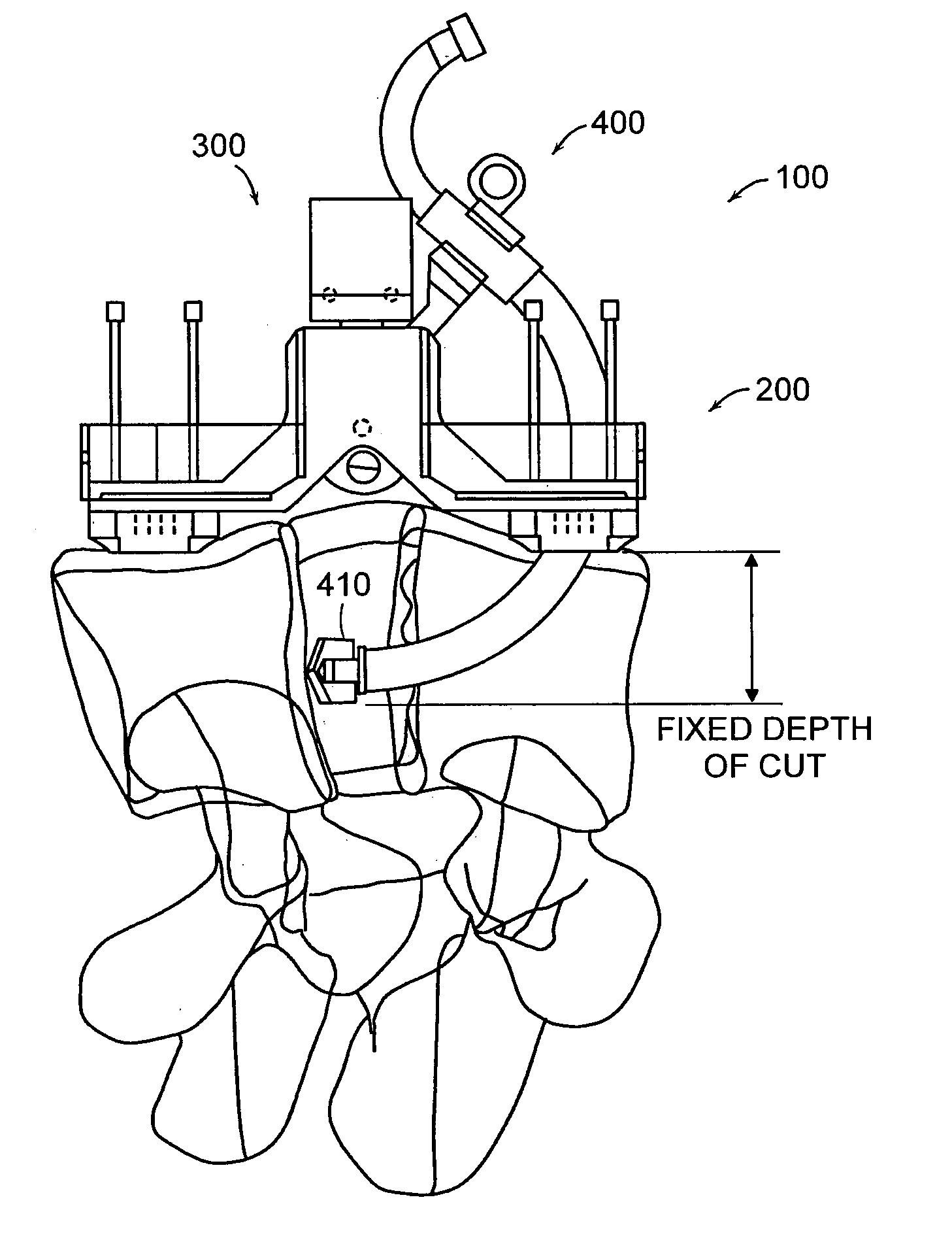
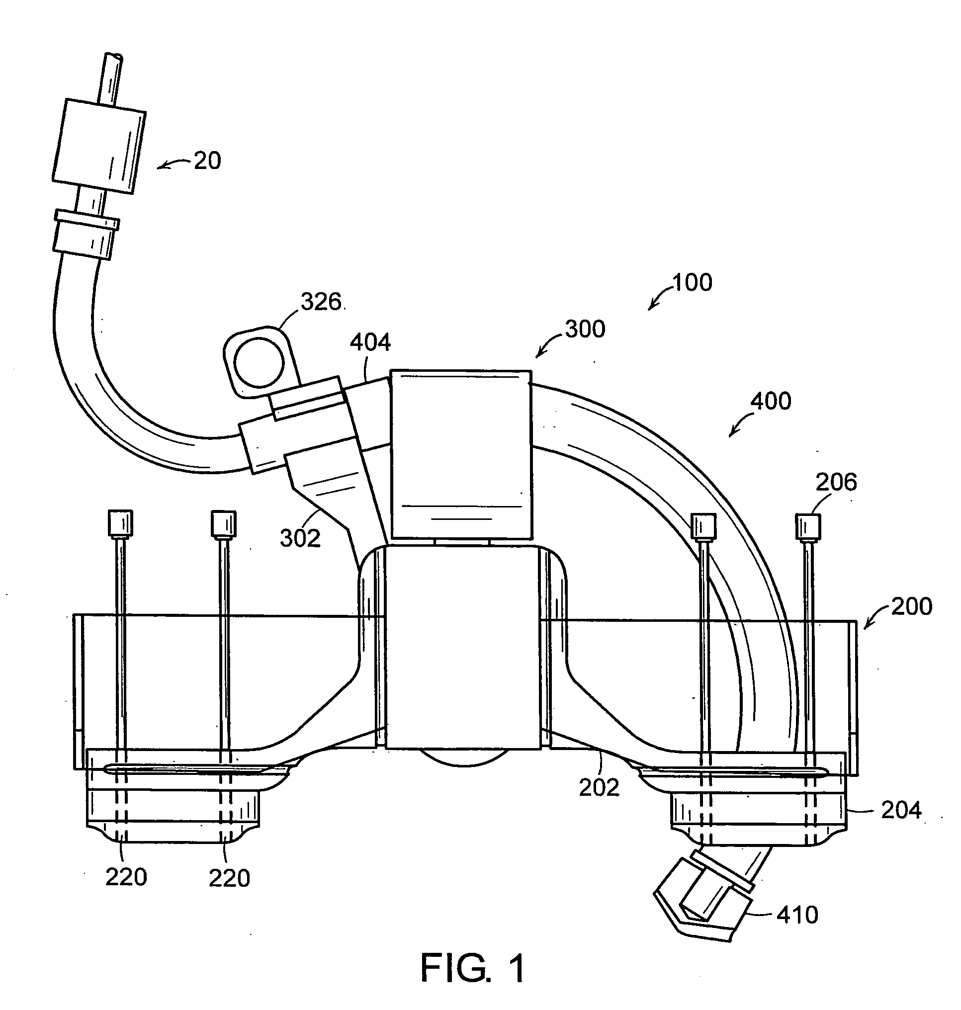
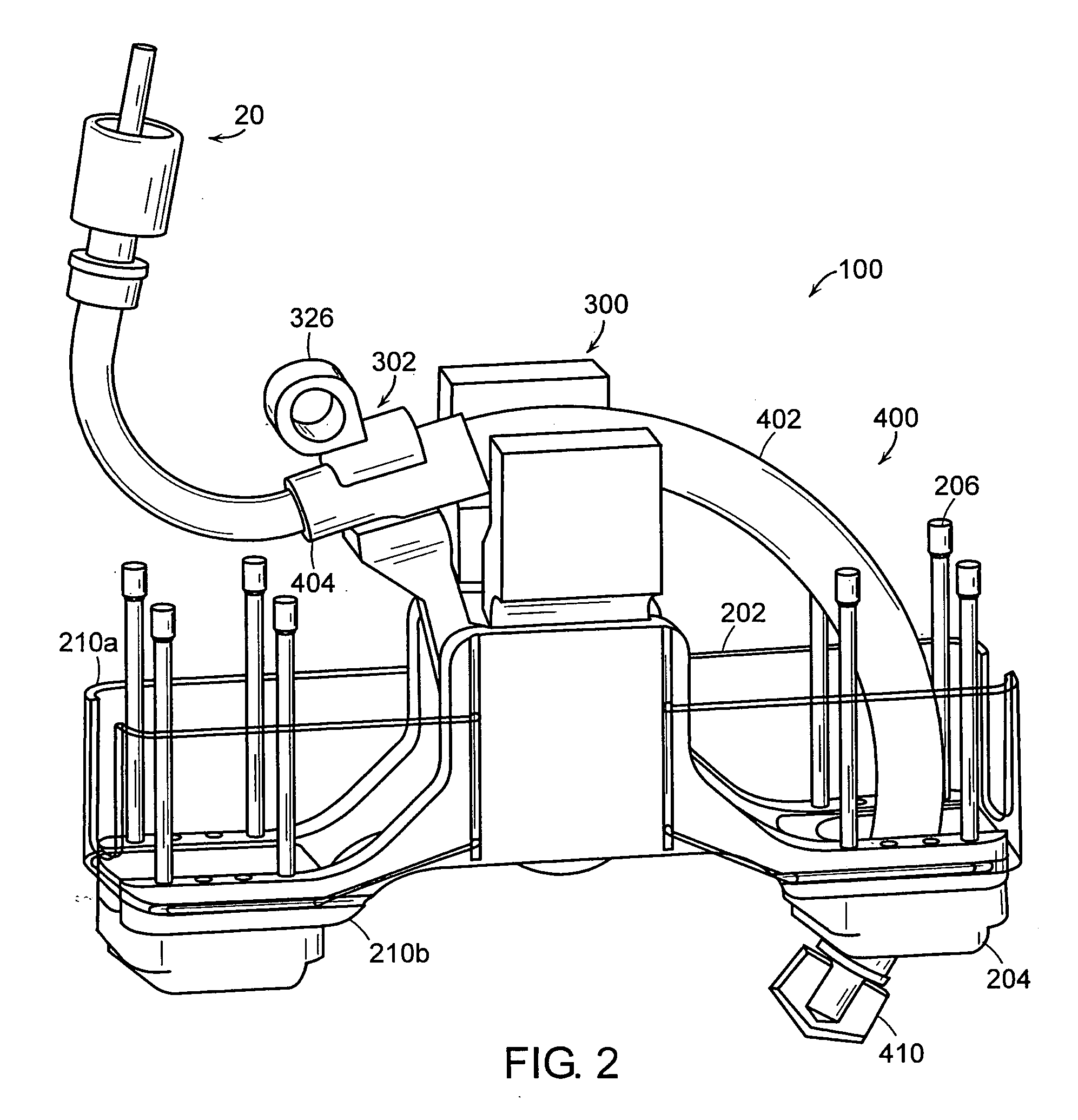
[0051] Referring now to the various figures of the drawing wherein like reference characters refer to like parts, there is shown in FIGS. 1-3 various views of a drilling apparatus 100 according to an aspect of the present invention that is generally comprised of a platform assembly 200, a pivot arm assembly 300 and drill assembly 400. As hereinafter described in more detail, the pivot arm assembly 300 is removably secured to the platform assembly 200 and the platform assembly is removably secured to the bone or bony structure so as to maintain the pivot point of the pivot arm assembly in general fixed relation to the bone or bony structure. The drill assembly 400 is removably secured to the pivot arm assembly 300 so as to maintain the end of the drill assembly including the bit 410 or drill end in fixed relation with respect to the pivot arm 302 of the pivot arm assembly. Consequently, as the pivot arm 302 is rotated about the pivot point, the bit 410 follows a predetermined arcuate...


PUM


Abstract

The present invention features new methods, apparatuses and devices for fixing adjacent bone segments, segments of a bony structure and adjacent vertebrate of a spine. The methods, apparatuses and devices utilize a new apparatus for forming a channel in a surface of the bone or bony structure segments or adjacent vertebra or a channel submerged within the bone or bony structure segments or adjacent vertebra. In more particular embodiments such apparatuses and methods including forming an arcuate channel and which channel can receive therein a curved rod or implant member, which also preferably is arcuate, and avoids the associated problems with prior cage or straight rod and screw systems. Also featured are systems, apparatuses and methods for repairing, replacing or augmenting the nucleus and/or annulus of a disc.

Description

[0001] This application claims the benefit of U.S. Provisional Application Ser. No. 60 / 512,134 filed Oct. 17, 2003, the teachings of which are incorporated herein by reference.FIELD OF INVENTION [0002] The present invention generally relates to methods, systems and apparatuses for bony fixation and more particularly to methods, systems and apparatuses adapted for fixing the bones of the spine. The present invention also generally relates to methods, systems and devices for augmenting, repairing or replacing the nucleus and / or annulus of an intervertebral disk of a spine, such as the spine of a mammalian body. BACKGROUND OF THE INVENTION [0003] Fixation or fusion of vertebral columns with bone or material, rods or plates is a common, long practiced surgical method for treating a variety of conditions. Many of the existing procedures involve the use of components that protrude outwardly, which may contact and damage a body part, such as the aorta, the vena cava, the sympathetic nerves...

Claims


Application Information

Patent Timeline
IPC IPC(8): A61BA61B17/00A61B17/16A61B17/17A61B17/32A61B17/58A61B17/88A61F2/44
CPCA61B17/1631A61B17/1642A61B17/1671A61F2/4455A61B17/32002A61B17/8875A61B17/1757
Inventor CARL, ALLENWINKLER, JOSEF K.BEISEL, ROBERT F.RAYMOND, SPANKY A.SAVAGE, DANIEL S.GROMEK, JASON J.NILSSON, CARL M.
Owner K2M
Why Eureka
Try Eureka