
Back emf actuator control

a back emf actuator and actuator technology, applied in the field of surface maintenance or conditioning machines, can solve the problems of negative impact of adding external components (sensors, limit switches, etc.) on machine reliability, and achieve the effects of less prone to breakage, easy maintenance, and low cos

Inactive Publication Date: 2005-12-01
TENNANT COMPANY
View PDF16 Cites 0 Cited by
  • Summary
  • Abstract
  • Description
  • Claims
  • Application Information

AI Technical Summary

Benefits of technology

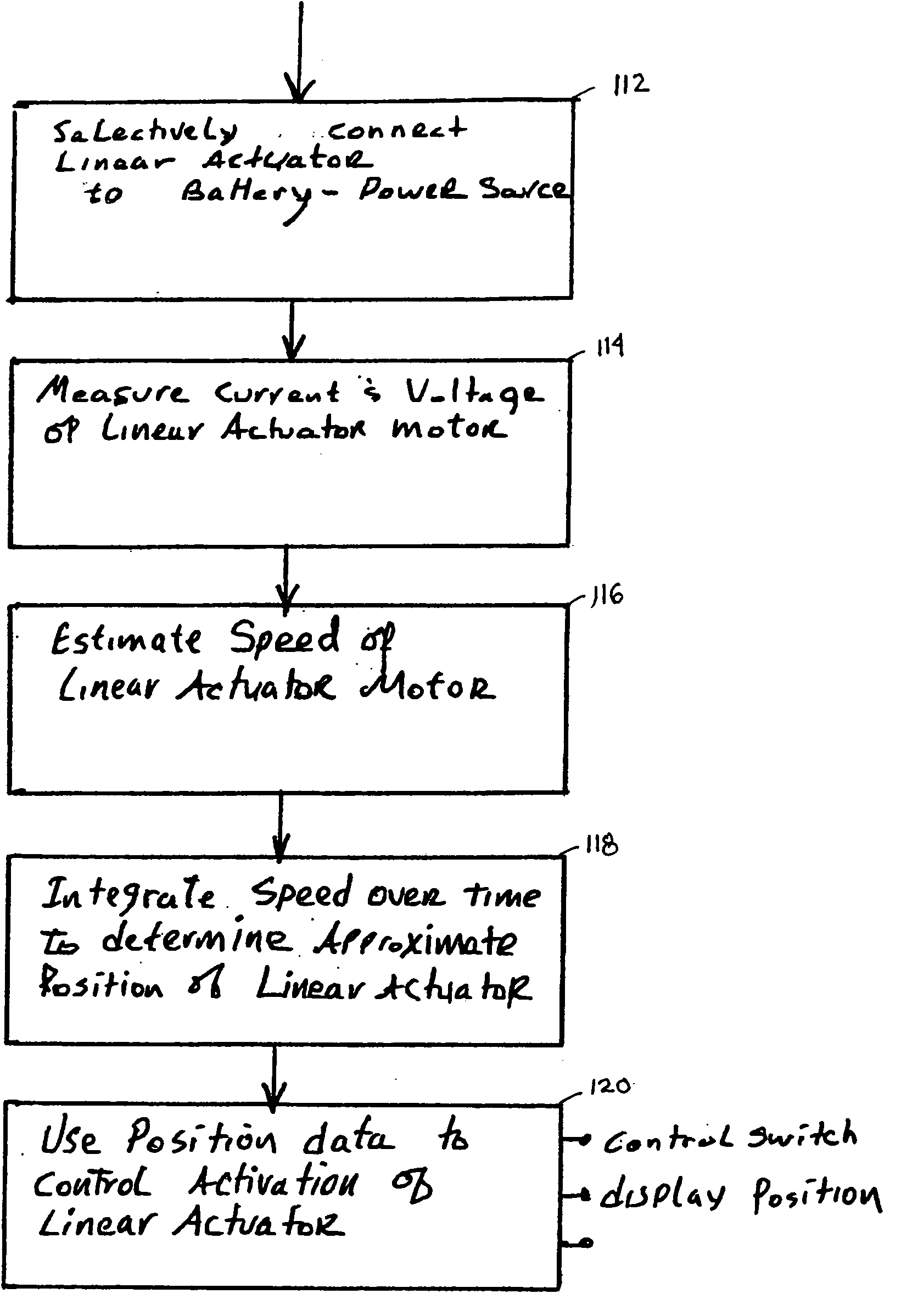
[0009] Estimating the position of the actuator is a key element in the control strategy of the present invention The reliability of a motion control system can be greatly enhanced by increasing the accuracy of the linear actuator position estimation according to the present invention. Adding external components (sensors, limit switches, etc.) has a negative impact on machine reliability. By monitoring actuator voltage and current, the impedance of the actuator motor can be mathematically determined (R=V / I). As the load on the motor changes, the relationship between the applied motor voltage and speed diminishes. The impedance of the motor is a more accurate indicator of speed, regardless of motor load.
[0011] The present invention provides several advantages over both prior art and contemporary apparatus for determining relative tool position. The present invention may be implemented without physical limit switches. As a result the present invention is generally lower cost, easier to maintain and less prone to breakage than prior art (and complex contemporary) cleaning head position determining mechanisms and algorithms.

Problems solved by technology

Adding external components (sensors, limit switches, etc.) has a negative impact on machine reliability.

Method used


Image

  • Back emf actuator control
  • Back emf actuator control
  • Back emf actuator control

Examples


Embodiment Construction

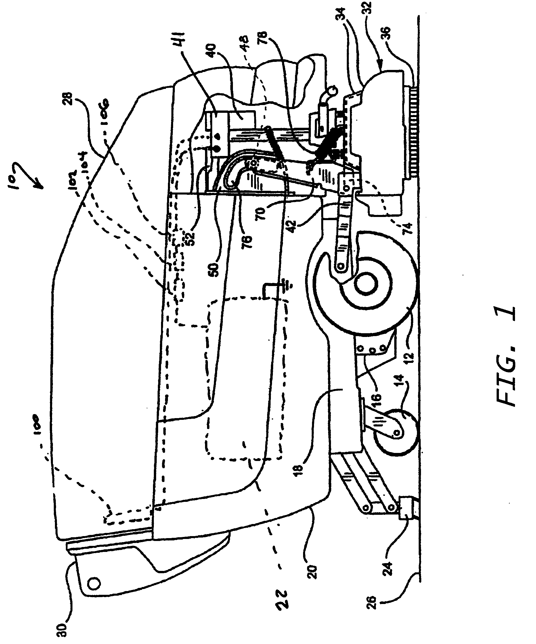
[0016] A floor scrubbing machine which uses the present invention is shown in normal operating position in FIG. 1. The scrubbing machine 10 has two front wheels 12 and two rear caster wheels 14, and a transaxle 16 providing traction drive to the front wheels. The transaxle and rear casters are attached to a frame 18, which supports a housing 20. This housing encloses rechargeable batteries 22 which supply energy to power the machine. It also contains a recovery tank to hold soiled scrub water recovered by a vacuum squeegee 24 from a floor 26 being scrubbed. A hinged lid 28 contains a tank for clean scrubbing solution to be dispensed to the floor and a vacuum fan to lift soiled scrub water from the floor via the squeegee 24 and deposit it in the recovery tank. A control console 30 provides necessary controls for an operator who walks behind the scrubber.

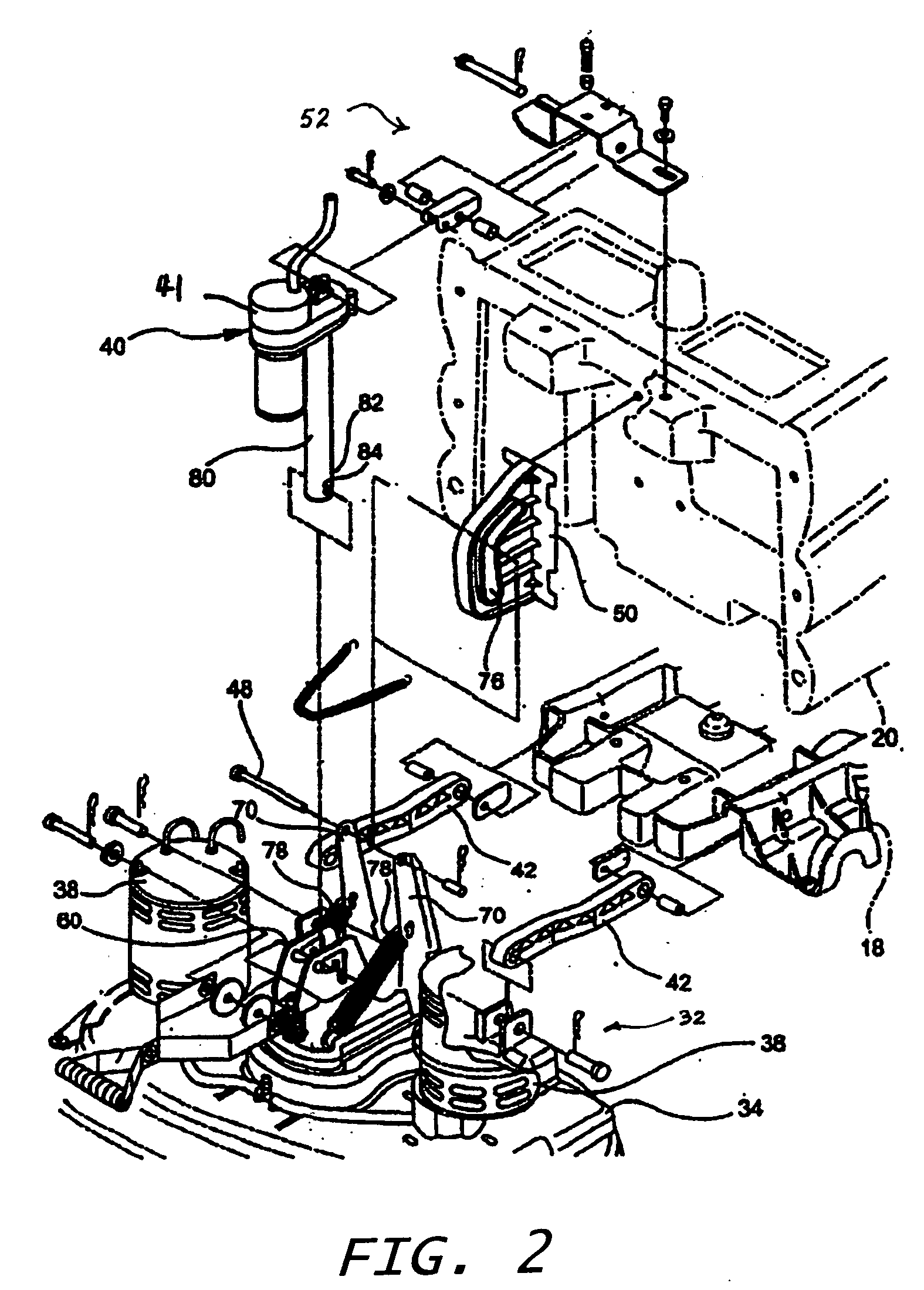
[0017] A scrub head 32 is shown in FIG. 1 in position to scrub the floor 26. A housing 34 encloses two scrub brushes 36. The brushe...


PUM


Abstract

A control system for estimating the approximate relative position of an electric linear actuator on a surface maintenance machine. The control system includes means for selectively coupling the electric motor of the linear actuator to the electric power source, means for measuring or estimating the current and voltage of the electric motor, means for estimating the motor speed based on the measured values of current and voltage, and storage means for storing values of estimated motor speed and integrating means for determining approximate linear actuator position, wherein the integrating means integrates the motor speed over time to determine the approximate position of the linear actuator position.

Description

FIELD OF THE INVENTION [0001] The present invention is directed to an apparatus and method of use for determining the approximate relative position of an actuator or tool controlled by the actuator and relates generally to surface maintenance or conditioning machines, and more particularly to those machines employing one or more surface maintenance or conditioning appliances or tools that perform one or more tasks including, among others, scrubbing, sweeping, and polishing or burnishing. BACKGROUND OF THE INVENTION [0002] Surface maintenance vehicles that perform a single surface maintenance or surface conditioning task are, of course, well known. Surface maintenance vehicles are generally directed to perform work in diverse maintenance, conditioning and cleaning applications such as for flooring surfaces. In this disclosure, the term floor refers to any support surface, such as, among others, floors, pavements, road surfaces, ship decks, and other surfaces to be cleaned and the lik...

Claims


Application Information

Patent Timeline
Patent Type & Authority Applications(United States)
IPC IPC(8): A47L11/40
CPCA47L11/4058A47L11/4011
Inventor ALOWONLE, MUSIBAU O.BUSHEY, BRUCE PHILLIPERKO, ROBERT J.GROSCHEN, PAUL LEONARD JR.MILUN, RICHARD F.
Owner TENNANT COMPANY
Learn More