Floor Covering And Locking Systems

a technology of locking system and floor covering, which is applied in the direction of load-supporting elements, structural elements, building components, etc., can solve the problems of large load on the locking system, continuous floor surface must as a rule be limited, and the load is particularly great in the passage between different rooms, so as to achieve better precision

Active Publication Date: 2005-12-08
VÄLINGE INNOVATION AB
View PDF99 Cites 126 Cited by
  • Summary
  • Abstract
  • Description
  • Claims
  • Application Information

AI Technical Summary

Benefits of technology

[0021] A first object of the present invention is to provide a floating floor of rectangular floorboards with mechanical locking systems, in which floor the size, pattern of laying and locking system of the floorboards cooperate and allow movements between the floorboards. According to an embodiment of the invention, the individual floorboards can change in shape after installation, i.e., shrink and swell due to changes in the relative humidity. This can occur in such a manner that the change in shape of the entire floor surface can be reduced or preferably be eliminated while at the same time the floorboards remain locked to each other without large visible joint gaps.
[0022] A second object is to provide locking systems, which allow a considerable movement between floorboards without large and deep dirt-collecting joint gaps and / or where open joint gaps could be excluded. Such locking systems are particularly suited for moisture sensitive materials, such as wood, but also when large floating floors are installed using wide and / or long floorboards.
[0027] According to several preferred embodiments of this invention, it is an advantage if the floor comprises rather small floorboards and many joints, which could compensate swelling and shrinking. The production tolerances should be rather small since well-defined plays and joint openings are generally required to produce a high quality floor according to the invention.
[0030] The most used equipment is an end tenor, double or single, where a chain and a belt are used to move the floorboard with great accuracy along a well defined feeding direction. Pressure shoes and support unites are used in many applications together with the chain and the belt mainly to prevent vertical deviations. Horizontal deviation of the floorboard is only prevented by the chain and the belt.
[0032] A third object of the present invention is to provide equipment and production methods which make it possible to produce floorboards and mechanical locking systems with an end tenor but with better precision than what is possible to accomplish with known technology.
[0033] Equipment for production of building panels, especially floorboards, comprises a chain, a belt, a pressure shoe and a tool set. The chain and the belt are arranged to displace the floorboard relative the tool set and the pressure shoe, in a feeding direction. The pressure shoe is arranged to press towards the rear side of the floorboard. The tool set is arranged to form an edge portion of the floorboard when the floorboard is displaced relative the tool set. One of the tools of the tool set forms a guiding surface in the floorboard. The pressure shoe has a guiding device, which cooperates with the guiding surface and prevents deviations in a direction perpendicular to the feeding direction and parallel to the rear side of the floorboard.

Problems solved by technology

The drawback is that the continuous floor surface must as a rule be limited even in the cases where the floor consists of relatively dimensionally stable floorboards, such as laminate floor with a fiberboard core or wooden floors composed of several layers with different fiber directions.
Without such a division, it is a risk that the floor when shrinking will change in shape so that it will no longer be covered by baseboards.
Also the load on the locking system will be great since great loads must be transferred when a large continuous surface is moving.
The load will be particularly great in passages between different rooms.
They collect dirt, give an unwanted appearance and are rather expensive.
Due to these limitations on maximum floor surfaces, laminate floorings have only reached a small market share in commercial applications such as hotels, airports, and large shopping areas.
Even if such an installation would be possible, the continuous floor surface must be restricted significantly.
This method of installation involving attachment to the subfloor has, however, a number of considerable drawbacks.
The main drawback is that as the floorboards shrink, a visible joint gap arises between the boards.
The joint gap can be relatively large, especially when the floorboards are made of moisture sensitive wood materials.
The installation methods are time-consuming, and in many cases the subfloor must be adjusted to allow gluing / nailing to the subfloor.
Small floorboards are however difficult to produce with the required tolerance since they have a tendency to turn in an uncontrolled manner during machining.
The main reason why small floorboards are more difficult to produce than large floorboards is that large floorboard has a much large area, which is in contact with a chain and a belt during the machining of the edges of the floorboards.
The problem is that in many applications this is not sufficient, especially when panels are small.

Method used


Image

  • Floor Covering And Locking Systems
  • Floor Covering And Locking Systems
  • Floor Covering And Locking Systems

Examples


first embodiment

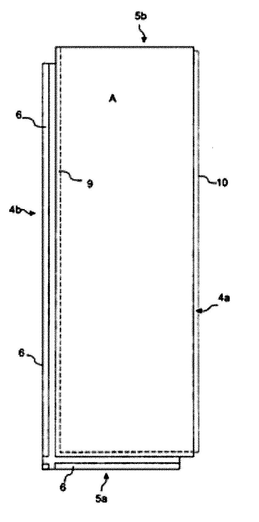
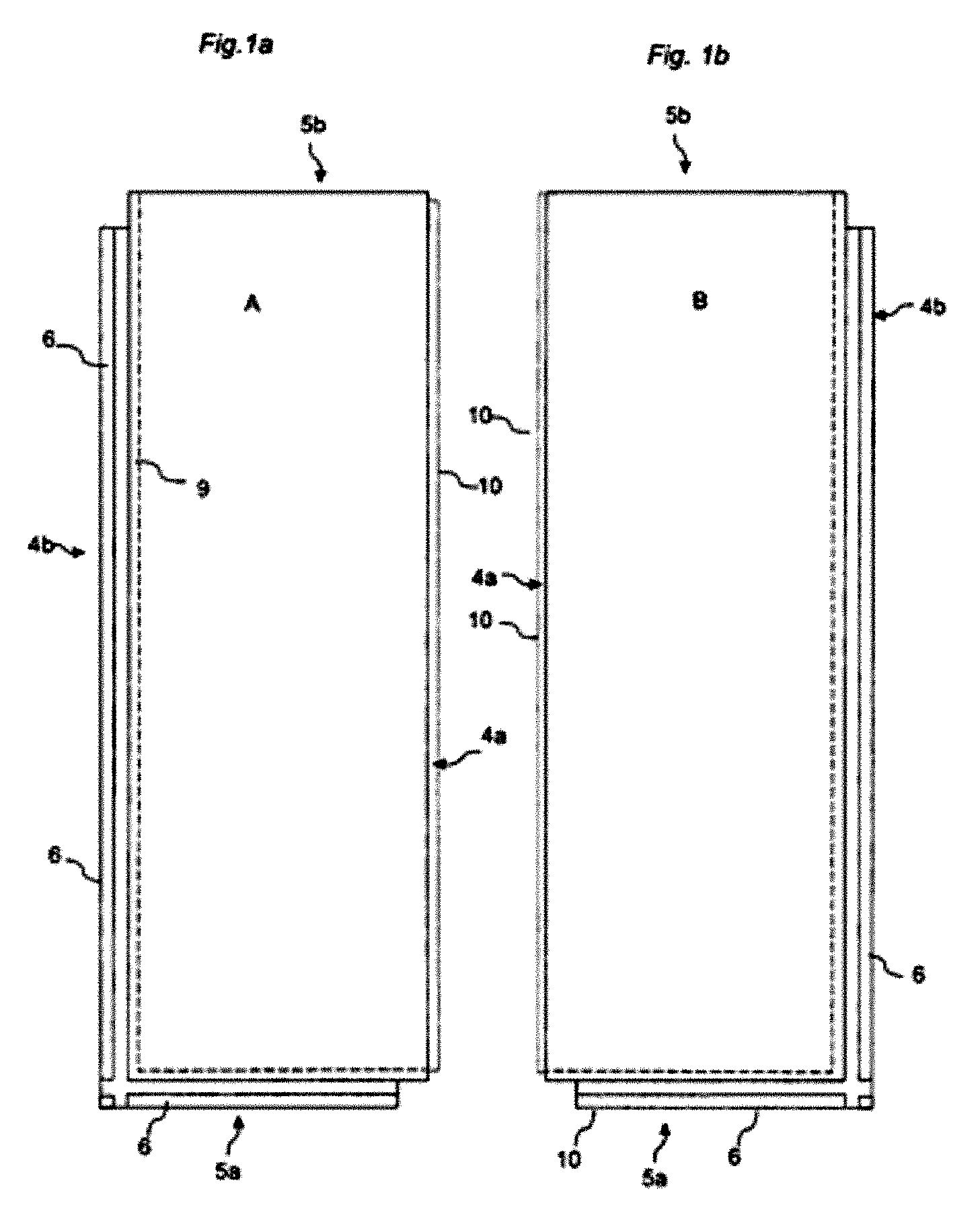
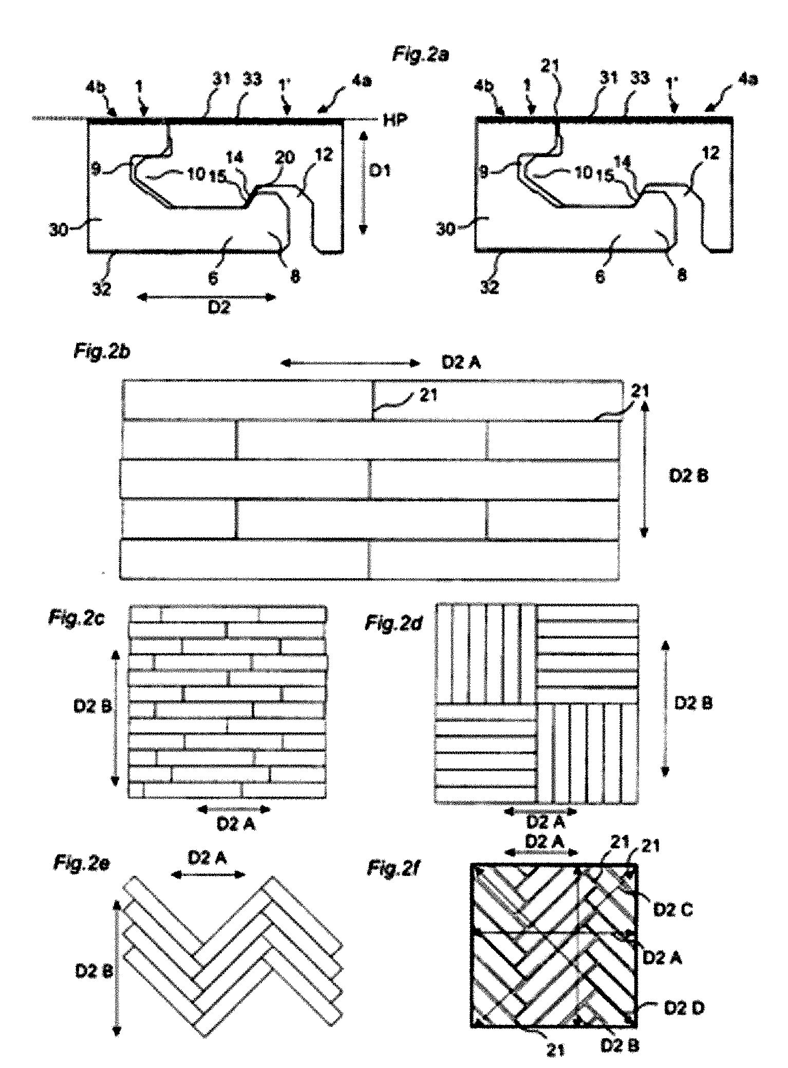
[0025] a floating floor comprises rectangular floorboards, which are joined by a mechanical locking system. The joined floorboards have a horizontal plane, which is parallel to the floor surface, and a vertical plane, which is perpendicular to the horizontal plane. The locking system has mechanically cooperating locks for vertical joining parallel to the vertical plane and for horizontal joining parallel to the horizontal plane of a first and a second joint edge. The vertical locks comprise a tongue, which cooperates with a groove, and the horizontal locks comprise a locking element with a locking surface cooperating with a locking groove. The format, installation pattern and locking system of the floorboards are designed in such a manner that a floor surface of 1 * 1 meter can change in shape in at least one direction at least 1 mm when the floorboards are pressed together or pulled apart. This change in shape can occur without visible joint gaps.

second embodiment

[0026] a locking system is provided for mechanical joining of floorboards, in which locking system the joined floorboards have a horizontal plane which is parallel to the floor surface and a vertical plane which is perpendicular to the horizontal plane. The locking system has mechanically cooperating locks for vertical joining parallel to the vertical plane and for horizontal joining parallel to the horizontal plane of a first and a second joint edge. The vertical locks comprise a tongue, which cooperates with a groove and the horizontal of a locking element with a locking surface, which cooperates with a locking groove. The first and the second joint edge have upper and lower joint edge portions located between the tongue and the floor surface. The upper joint edge portions are closer to the floor surface than the lower. When the floorboards are joined and pressed against each other, the two upper joint edge portions are spaced from each other and one of the upper joint edge porti...


PUM


Abstract

Abstract of the Disclosure Floorboards with a mechanical locking system that allows movement between the floorboards when they are joined to form a floating floor.

Description

Detailed Description of the InventionCross-Reference to Related Applications[0001] The present application claims priority of Swedish Patent Application No. 0400068-3, filed in Sweden on January 13, 2004 and U.S. Provisional Application No. 60 / 537,891, filed in the United States on January 22, 2004, the entire contents of which are hereby incorporated herein by reference.Field of the Invention[0002] The invention relates generally to the technical field of locking systems for floorboards. The invention concerns on the one hand a locking system for floorboards which can be joined mechanically and, on the other hand, floorboards and floor systems provided with such a locking system and a production method to produce such floorboards.[0003] The present invention is particularly suited for use in floating wooden floors and laminate floors, such as massive wooden floors, parquet floors, floors with a surface of veneer, laminate floors with a surface layer of high pressure laminate or dir...

Claims


Application Information

Patent Timeline
Patent Type & Authority Applications(United States)
IPC IPC(8): B27F5/02B27M3/04E04C3/00E04C3/30E04F15/02E04F15/04
CPCB27F5/026B27M3/04E04F15/02033E04F15/02038E04F15/04E04F2201/05E04F2201/0138E04F2201/0153E04F2201/025E04F2201/026E04F2201/041E04F2201/0115
Inventor PERVAN, DARKO
Owner VÄLINGE INNOVATION AB
Why Eureka
Try Eureka