Device and process for cleaning electrified contact rail insulators for rail rapid transit systems

a technology for electrified contact rails and rapid transit systems, applied in the direction of carpet cleaners, cleaning using liquids, vehicle cleaning, etc., can solve the problems of limiting the access to the insulator, slow cleaning, expensive, etc., and achieves the effect of low-cost cleaning and fast cleaning

Inactive Publication Date: 2005-12-08
VOHRA ARUN
View PDF3 Cites 34 Cited by
  • Summary
  • Abstract
  • Description
  • Claims
  • Application Information

AI Technical Summary

Benefits of technology

[0006] The invention relates to a cleaning device and process for fast, l

Problems solved by technology

Anchors, brackets and cables also limit access to the insulators.
Cleaning with hand brushes, cleaning pads, or pressure washing (and blow drying with compressed air to prevent wet surfaces from conducting electricity) is slow, costly, and not fully effective.
The problem is that electrically conducting particulates and dirt adhere to the insulators.
Rust and brake shoe particles also coat the insulators.
The insulators eventually fail and arc, producing smoke and flame.
If the insulator is made of fiberglass, it can burn.
Porcelain insulators can become red hot and melt.
The hot insulators can cause wood ties to catch on fire.
The reduced support to the running rails due to a burnt out tie, may cause a derailment of the railcar and train with catastrophic results.
The contact rail cover guard is typically made of fiberglass, and it can also burn.
A failed insulator can cause the electric supply cable to overheat and cause the plastic cable covering to smoke and burn.
The loss of income to the rail system and lost time

Method used


Image

  • Device and process for cleaning electrified contact rail insulators for rail rapid transit systems
  • Device and process for cleaning electrified contact rail insulators for rail rapid transit systems
  • Device and process for cleaning electrified contact rail insulators for rail rapid transit systems

Examples


Embodiment Construction

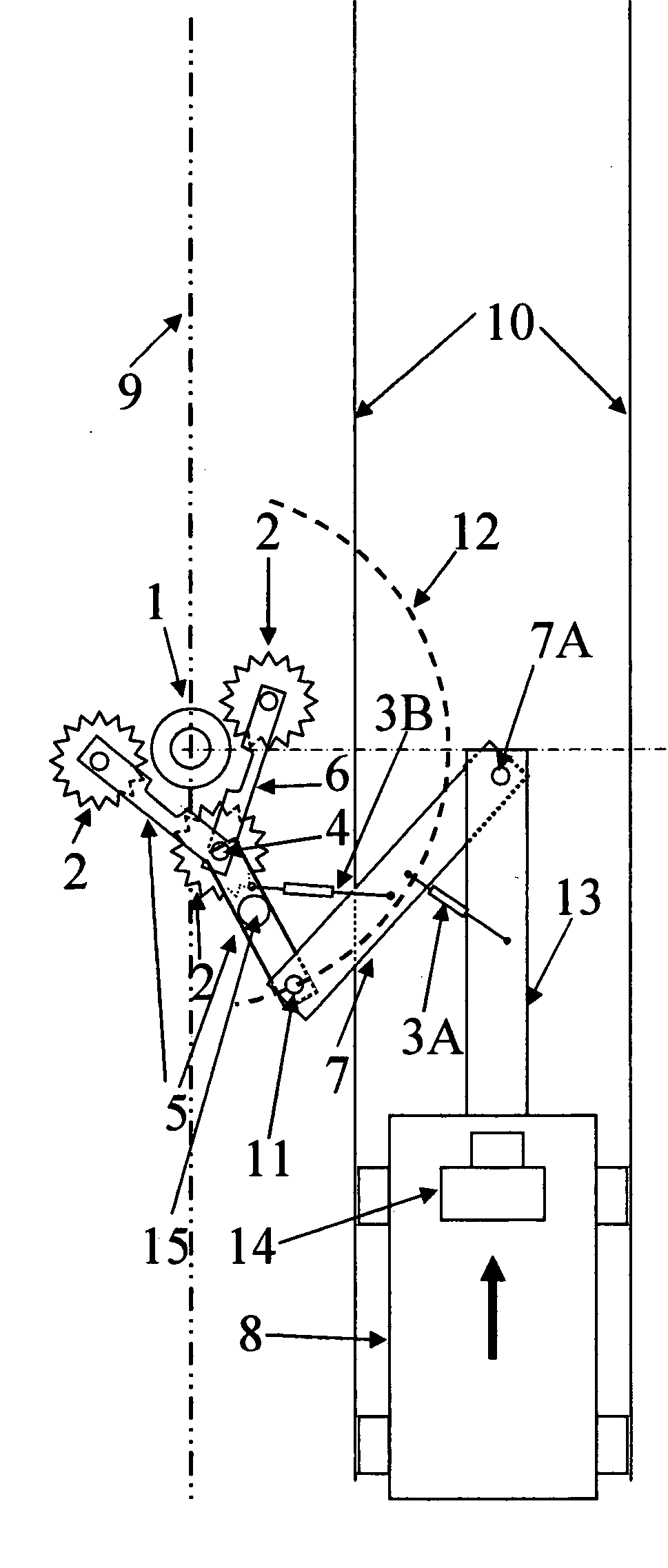
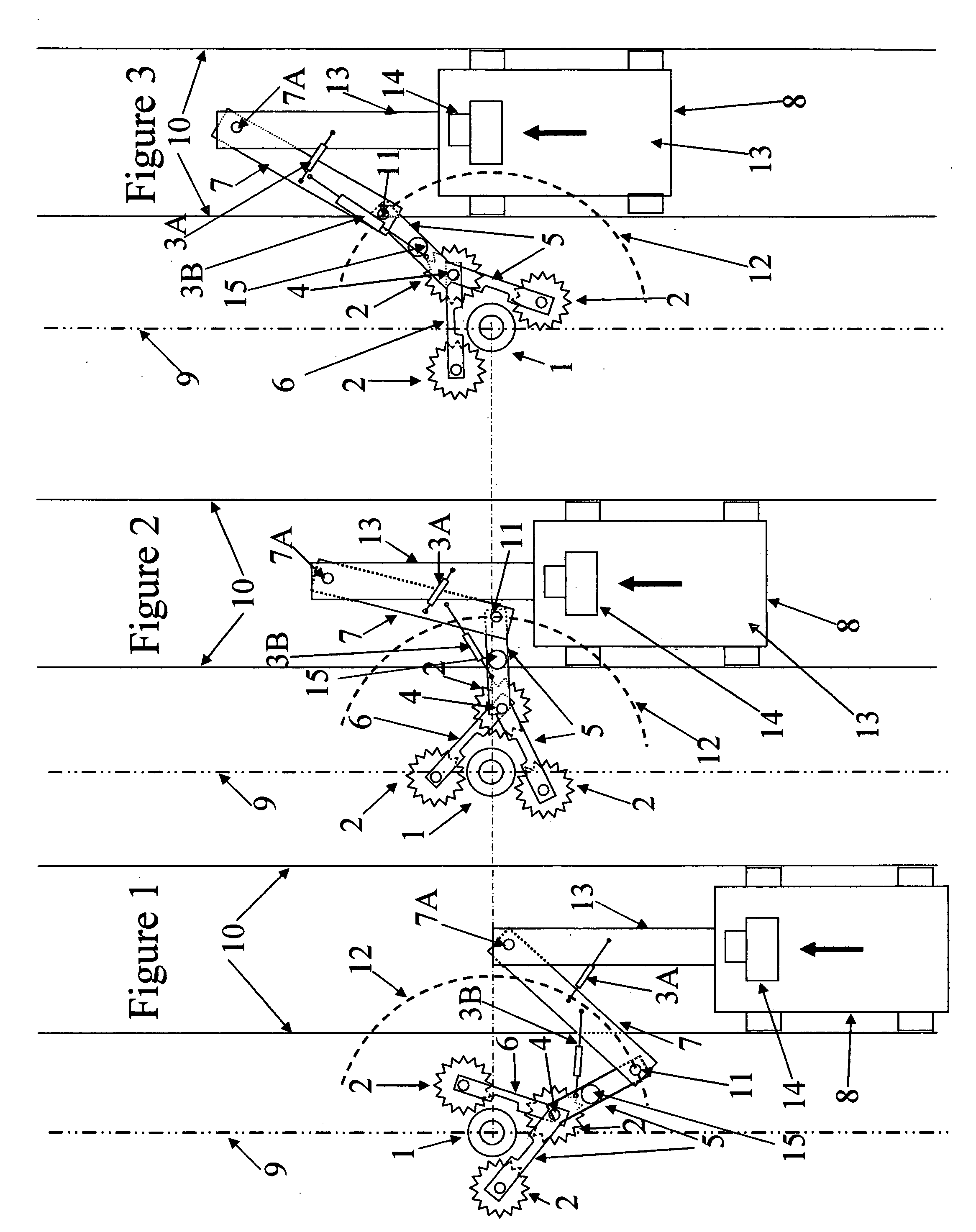
[0035] The device of the invention uses a positioning arm, preferably an articulated arm with at least two members connected by a hinge or pin to connect a service vehicle to a cleaning station. The cleaning station is connected to one end of the articulated arm with a hinge or pin so that it is capable of angular movement along a vertical axis around the insulator. The cleaning station has one or more fingers, which may be fixed or movable, that contact the insulator and bring the cleaning tools attached to the one or more fingers into operative proximity to the insulator. The one or more fingers may form a locking mechanism as in FIG. 9 that embraces the insulator.

[0036] There are several types of cleaning stations, with attached cleaning tools such as powered rotating, reciprocating, vibrating, oscillating and / or linear brushes, wrap around cleaning belts, sonic horns, ultrasonic vibrating guns, laser or laser scanners, pressure washing and / or water jetting nozzles on stationary...


PUM


Abstract

A device and process for cleaning electrical insulators mounted under an electrified contact rail parallel to a rail track comprises positioning arm(s) attached to a vehicle that travels on the track and a cleaning station with fixed or moveable fingers. The fingers have attached cleaning tools and engage, operate on, partly rotate around the circumference of the insulator, and disengage, as the vehicle passes by the insulator. The cleaning station can also ride on the contact rail and have moveable vertical members with cleaning tools attached to L-shaped tool holders that rotate around a portion of the circumference of the insulator. Cleaning tools include powered rotating, reciprocating, vibrating, oscillating and/or linear brushes, wrap-around cleaning belts, sonic horns, ultrasonic vibrating guns, lasers, pressure washing and/or water jetting nozzles on stationary, rotating or oscillating spray bars and spinning heads using steam, tap or deionized water, and pneumatic polishing nozzles.

Description

BACKGROUND OF THE INVENTION [0001] The invention relates to a device for cleaning electrified contact (or third) rail insulators for rail rapid transit systems to prevent arcing and smoke. There may be one or two contact rails. The contact rail typically carries over 700 volts and sits on porcelain or fiberglass composite insulators. The contact rail often has a safety cover that limits access to the insulators. Anchors, brackets and cables also limit access to the insulators. Cleaning with hand brushes, cleaning pads, or pressure washing (and blow drying with compressed air to prevent wet surfaces from conducting electricity) is slow, costly, and not fully effective. [0002] The problem is that electrically conducting particulates and dirt adhere to the insulators. Normal maintenance of the tracks includes rail grinding that generates a significant amount of iron particulates that coat the insulators. Rust and brake shoe particles also coat the insulators. Snow and highway deicing s...

Claims


Application Information

Patent Timeline
IPC IPC(8): B08B1/00B08B1/04B08B3/02B08B7/00B08B7/02B60M1/02E01H8/10H01B17/52
CPCB08B1/008B08B3/024E01H8/10B08B7/02B60M1/02B08B7/0042
Inventor VOHRA, ARUN
Owner VOHRA ARUN
Why Eureka
Try Eureka