
Magnetorheological reconfigurable clamp for a flexible manufacturing system

a flexible manufacturing system and magnetic reconfiguration technology, applied in manufacturing tools, soldering devices, auxillary welding devices, etc., can solve the problems of long time required for reconfiguration, modular fixtures that have no intrinsic ability to adapt to different sizes and shapes of parts within a part family, and modular fixtures generally lack rigidity

Inactive Publication Date: 2005-12-08
GM GLOBAL TECH OPERATIONS LLC
View PDF5 Cites 44 Cited by
  • Summary
  • Abstract
  • Description
  • Claims
  • Application Information

AI Technical Summary

Benefits of technology

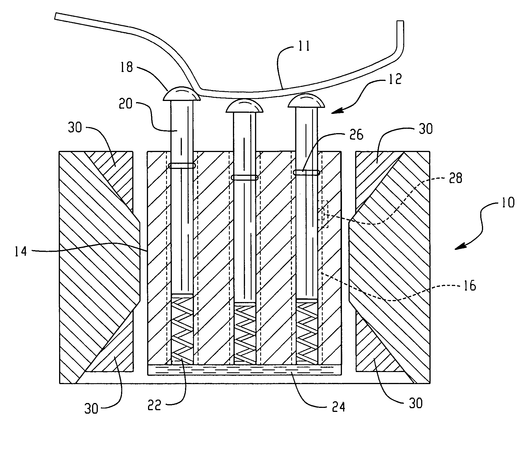
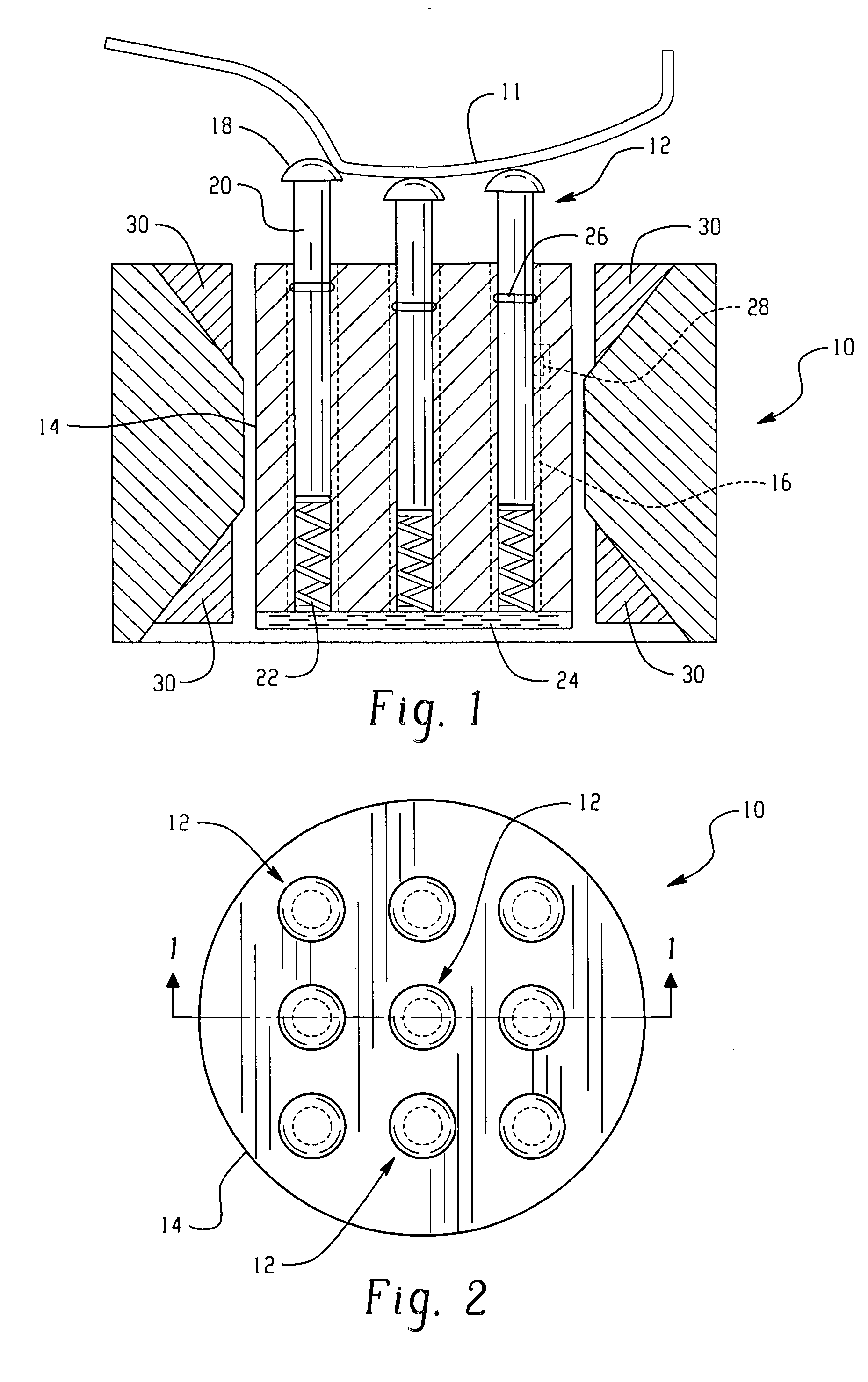
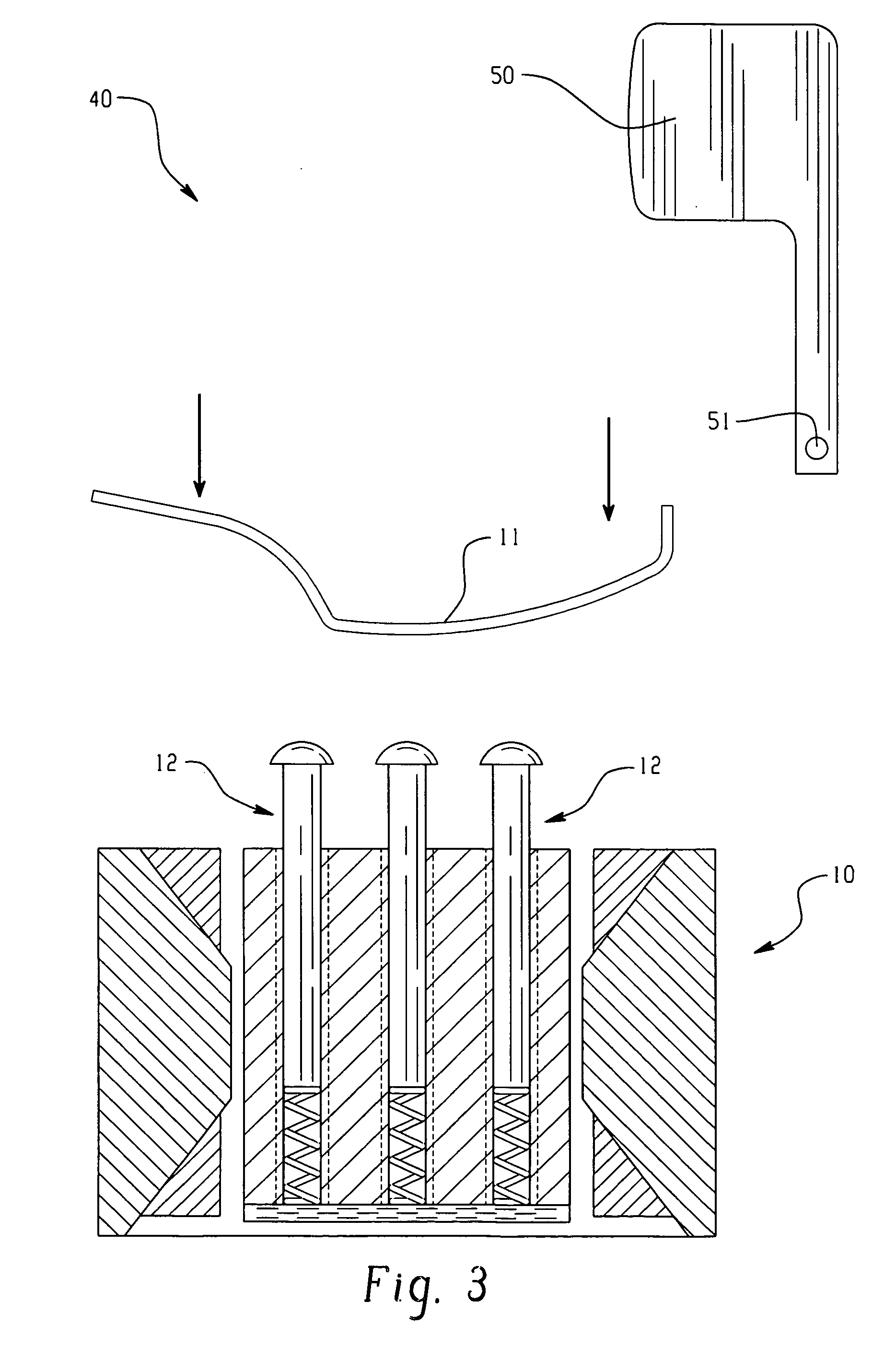
The patent describes a reconfigurable clamp system that can be used to hold a workpiece in place. The clamp has a body with pins that are slidably engaged within sleeves. A compression spring is attached to each pin, and a reservoir contains a special fluid that can change its properties when exposed to an electromagnet. The clamp can be adjusted to conform to the surface of the workpiece, and the fluid can be used to control the force between the pins and the sleeves. This system can provide a flexible and effective way to hold workpieces in place during manufacturing processes.

Problems solved by technology

However, modular fixtures have no intrinsic ability to adapt to different sizes and shapes of parts within a part family.
In addition, the time necessary for reconfiguration is long and modular fixtures generally lack stiffness.
While an excellent means of facilitating the holding of complex parts, encapsulation is a costly and time-consuming process.
To date, however no feasibility studies have been conducted regarding the applicability of any of these techniques to production machining operations.
One troublesome area in flexible manufacturing systems is its implementation in body shops.
Clamps are typically employed to support the various sheet metal workpieces, e.g., body panels, during assembly and clamping can potentially scratch the exposed surface and / or locally deform the workpiece, affecting its aesthetic quality.
While, ideally, clamping could be performed on flanges or surfaces that are invisible or immaterial to end users, some clamping inevitably occurs on exposed surfaces.
A problem arises if multiple models are produced having significantly different workpiece configurations.

Method used


Image

  • Magnetorheological reconfigurable clamp for a flexible manufacturing system
  • Magnetorheological reconfigurable clamp for a flexible manufacturing system
  • Magnetorheological reconfigurable clamp for a flexible manufacturing system

Examples


Embodiment Construction

[0018] Disclosed herein is a magnetorheological reconfigurable clamp system for providing support and securement of a variety of dissimilar workpieces. Although reference will be made to its use in fixturing automotive body panels, it should be understood that the magnetorheological reconfigurable clamp system could be employed for a variety of end use applications where it may be desirable to support dissimilar workpieces without requiring manual adjustment or reprogramming. For example, the magnetorheological reconfigurable clamp system can be employed in flexible manufacturing systems for thin walled and / or thick walled objects, contoured and / or planar objects, on exterior surfaces as well as on hidden surfaces, and the like. Advantageously, the magnetorheological reconfigurable clamp system can be used on exposed surfaces of body panels without marring, scratching and / or causing local deformations.

[0019] The following description of the preferred embodiments is merely exemplary...


PUM

PropertyMeasurementUnit
sizesaaaaaaaaaa
sizesaaaaaaaaaa
sizesaaaaaaaaaa

Abstract

A reconfigurable clamp for a flexible manufacturing system comprises a body portion, a plurality of pins slidably engaged within sleeves formed in the body portion, a compression spring attached to each shaft of the plurality of pins, a reservoir comprising a magnetorheological fluid in operative communication with the plurality of pins, and an electromagnet in operative communication with the magnetorheological fluid, wherein the electromagnet selectively increases a yield stress property of the magnetorheological fluid; and a matching pressure foot.

Description

CROSS REFERENCE TO RELATED APPLICATIONS [0001] This application relates to, and claims priority to, provisional U.S. Application No. 60 / 576,923 filed on Jun. 4, 2004, hereby incorporated by reference in its entirety.BACKGROUND [0002] The present disclosure generally relates to a flexible manufacturing system for vehicle assembly, and more particularly, to a magnetorheological reconfigurable clamp for providing support for a variety of different body panel configurations employed in the vehicle assembly without requiring manual adjustment or reprogramming. [0003] The advent of assembly lines has enabled rapid, mass production of products at a reduced product cost. Assembly lines typically include multiple operation stages with component, material or sub-assembly inputs. Sometimes the workpieces are similar or related part shapes. Other times, the workpieces are of unrelated design but require similar manufacturing operations. In these varied applications, the fixture reconfiguration ...

Claims


Application Information

Patent Timeline
Patent Type & Authority Applications(United States)
IPC IPC(8): B23K11/11B23K37/04B23K37/047B25B1/24B25B5/16
CPCB23K11/11B23K37/0435B25B1/2421B23K37/047B23Q1/035B23K37/0443
Inventor SEARS, IVAN G.STEVENSON, ROBINMENASSA, ROLAND J.
Owner GM GLOBAL TECH OPERATIONS LLC
Learn More