Imaging lens

a technology of imaging lens and optical lens, which is applied in the field of imaging lens, can solve the problems of inability to produce compact lenses, inability to reduce the effective diameter of the third lens, and long distance (optical length) from the surface of the first lens on the object side to the imaging surface, etc., and achieves the effect of reducing the abbe number, and reducing the distan

Inactive Publication Date: 2005-12-08
MILESTONE CO LTD
View PDF1 Cites 14 Cited by
  • Summary
  • Abstract
  • Description
  • Claims
  • Application Information

AI Technical Summary

Benefits of technology

[0050] Polycarbonate has a higher refractivity and a smaller Abbe number than cycloolefin plastics. Hence, by forming the first lens L1 and third lens L3 from cycloolefin plastics and forming the second lens L2 from polycarbonate, the optical length can be shortened, and the resolution can be further increased.
[0051] Moreover, by constituting the first lens L1 and third lens L3 by lenses formed using cycloolefin plastics, constituting the second lens L2 by a lens formed using polycarbonate, and constituting the third lens L3 by a lens having a negative refractive power and a meniscus shape in which the convex surface faces the object side, the optical length can be shortened more reliably, and an imaging lens having a high resolution can be realized. This will be described in further detail below.

Problems solved by technology

However, the refractive power of these three lenses, which are constituted by first, second, and third lenses arrayed in succession from the object side, is positive in the first lens, negative in the second lens, and positive in the third lens, and hence the distance (optical length) from the surface of the first lens on the object side to the imaging surface is too long.
Further, a diaphragm is disposed on the object-side surface of the first lens, and hence the effective diameter of the third lens cannot be reduced.
As a result, a compact lens cannot be produced.
Hence, although these imaging lenses are set with a short combined imaging lens focal length, the back focus is long, and thus the optical length is too long.
In addition, these lenses use glass materials, and are therefore expensive.
In addition, the lenses use glass materials, and are therefore expensive.
However, the refractive power of the three lenses in this imaging lens, which are arranged as first, second, and third lenses in succession from the object side, is weak in the first lens, weak in the second lens, and positive in the third lens, and hence the refractive power of the first lens and second lens cannot be fully compensated for by the third lens alone.
As a result, the back focus lengthens, causing an increase in the optical length.
Furthermore, the third lens uses a glass material, and hence cost reduction is incomplete.
This is unsuitable for installation in image input devices of portable telephones or personal computers, digital cameras, CCD cameras used for monitoring purposes, surveying devices, and so on.
Since the angle of incidence of the light entering an intermediate position from the peripheral portion of the lens, which forms an important part of an image, deviates greatly from a right angle, the light enters the imaging device in a diagonal direction to the imaging device, thereby increasing the amount of reflection on the entrance surface such that the light reaching a photoelectric conversion surface of the imaging device is low in energy.
As a result, this part of the image becomes dark.

Method used


Image

  • Imaging lens
  • Imaging lens
  • Imaging lens

Examples


embodiment 1

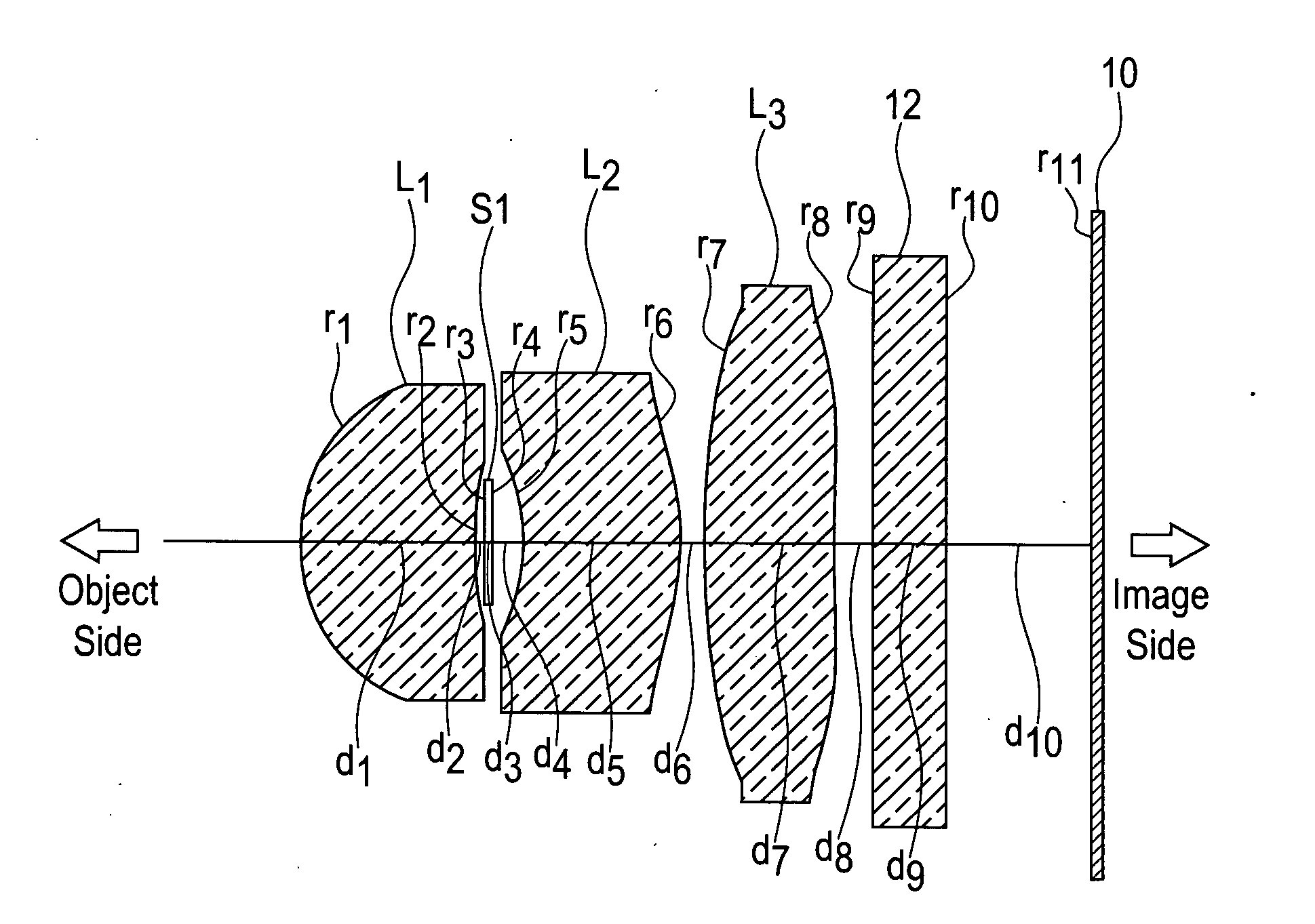
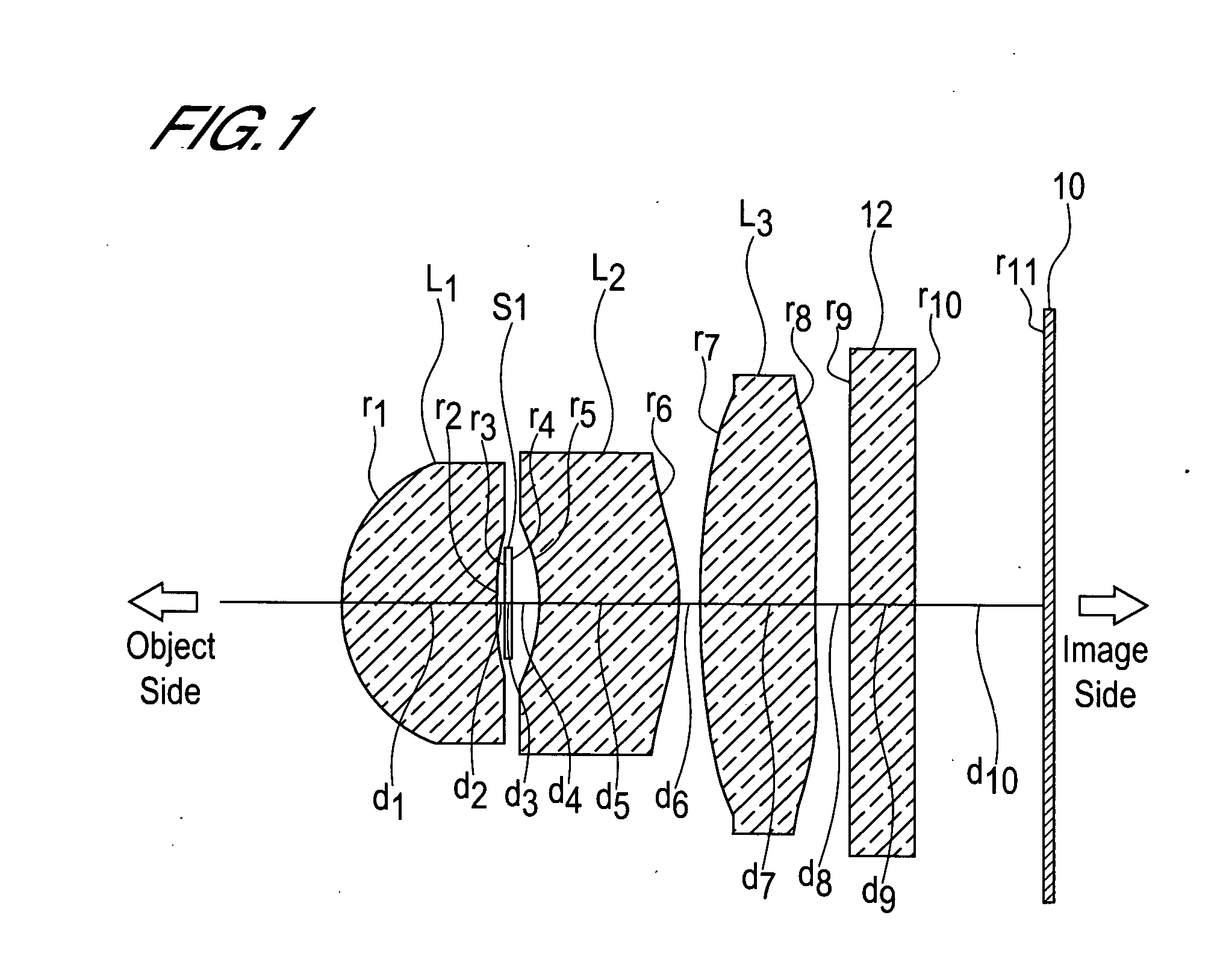
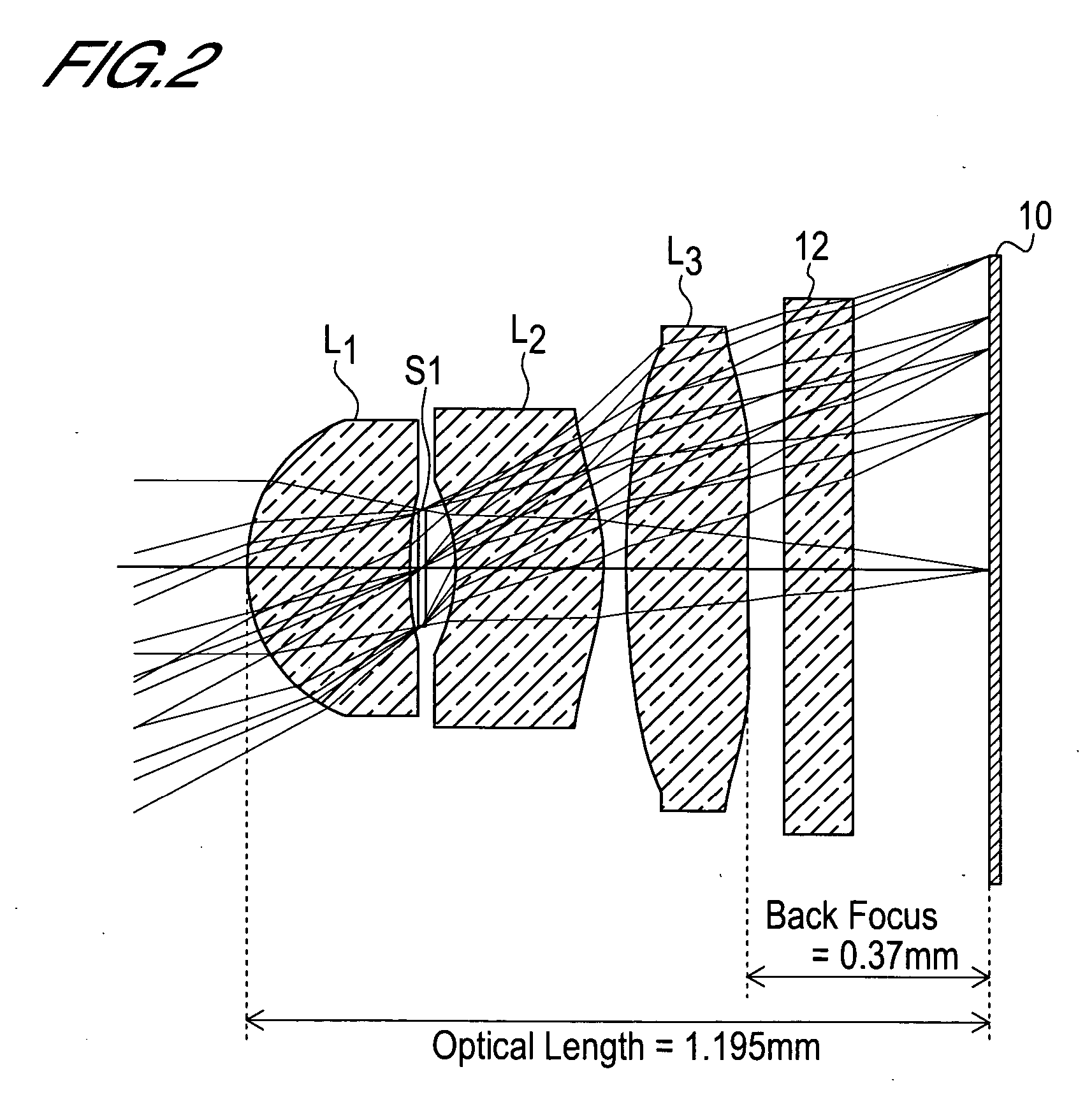
[0115] (A) The object-side radius of curvature r1 of the first lens L1 is r1=0.296 mm. [0116] (B) The image-side radius of curvature r2 of the first lens L1 is r2=0.720 mm. [0117] (C) The back focus bf is bf=0.365 mm. [0118] (D) The distance through the atmosphere from the object-side surface of the first lens L1 to the imaging surface, or in other words the optical length d, is d=d1+d2+d3+d4+d5+d6+d7+bf=1.195 mm. [0119] (E) The distance D2 between the first lens L1 and second lens L2 is D2=d2+d3+d4=0.076 mm. [0120] (F) The distance D4 between the second lens L2 and third lens L3 is D4=d6=0.0369 mm. [0121] (G) The focal length f1 of the first lens L1 is f1=0.79 mm. [0122] (H) The focal length f2 of the second lens L2 is f2=−5.14 mm. [0123] (I) The focal length f3 of the third lens L3 is f3=10.56 mm.

[0124] Hence [0125] (1) r1 / r2=0.296 / 0.720=0.4111 [0126] (2) D2 / f=0.076 / 1.00=0.076 [0127] (3) D4 / f=0.0369 / 1.00=0.0369 [0128] (4) d / f=1.195 / 1.00=1.195, and [0129] (5) bf / f=0.365 / 1.00=0.365...

embodiment 2

[0139] (A) The object-side radius of curvature r1 of the first lens L1 is r1=0.300 mm. [0140] (B) The image-side radius of curvature r2 of the first lens L1 is r2=0.748 mm. [0141] (C) The back focus bf is bf=0.362 mm. [0142] (D) The distance through the atmosphere from the object-side surface of the first lens L1 to the imaging surface, or in other words the optical length d, is d=d1+d2+d3+d4+d5+d6+d7+bf=1.204 mm. [0143] (E) The distance D2 between the first lens L1 and second lens L2 is D2=d2+d3+d4=0.078 mm. [0144] (F) The distance D4 between the second lens L2 and third lens L3 is D4=d6=0.0232 mm. [0145] (G) The focal length f1 of the first lens L1 is f1=0.79 mm. [0146] (H) The focal length f2 of the second lens L2 is f2=−3.57 mm. [0147] (I) The focal length f3 of the third lens L3 is f3=5.96 mm.

[0148] Hence [0149] (1) r1 / r2=0.300 / 0.748=0.4011 [0150] (2) D2 / f=0.078 / 1.00=0.078 [0151] (3) D4 / f=0.0232 / 1.00=0.0232 [0152] (4) d / f=1.204 / 1.00=1.204, and [0153] (5) bf / f=0.362 / 1.00=0.362....

embodiment 3

[0162] (A) The object-side radius of curvature r1 of the first lens L1 is r1=0.296 mm. [0163] (B) The image-side radius of curvature r2 of the first lens L1 is r2=0.738 mm. [0164] (C) The back focus bf is bf=0.337 mm. [0165] (D) The distance through the atmosphere from the object-side surface of the first lens L1 to the imaging surface, or in other words the optical length d, is d=d1+d2+d3+d4+d5+d6+d7+bf=1.221 mm. [0166] (E) The distance D2 between the first lens L1 and second lens L2 is D2=d2+d3+d4=0.09 mm. [0167] (F) The distance D4 between the second lens L2 and third lens L3 is D4=d6=0.0215 mm. [0168] (G) The focal length f1 of the first lens L1 is f1=0.78 mm. [0169] (H) The focal length f2 of the second lens L2 is f2=−6.27 mm. [0170] (I) The focal length f3 of the third lens L3 is f3=8.56 mm.

[0171] Hence [0172] (1) r1 / r2=0.296 / 0.738=0.4011 [0173] (2) D2 / f=0.09 / 1.00=0.09 [0174] (3) D4 / f=0.0215 / 1.00=0.0215 [0175] (4) d / f=1.221 / 1.00=1.221, and [0176] (5) bf / f=0.337 / 1.00=0.337.

[0...


PUM


Abstract

The present invention is an imaging lens in which various aberrations are favorably corrected, the optical length is short, and a sufficient back focus is secured. The imaging lens is constituted by arranging a first lens L1, an aperture diaphragm S1, a second lens L2, and a third lens L3 in succession from the object side to the image side. The first lens L1 is a lens having a positive refractive power and a meniscus shape in which the convex surface faces the object side, the second lens L2 is a lens having a negative refractive power and a meniscus shape in which the convex surface faces the image side, and the third lens L3 is a lens in which the convex surface faces the object side. The imaging lens satisfies the following conditions:
    • 0.35<r1/r2<0.45 (1)
    • 0.07<D2/f<0.1 (2)
    • 0.01<D4/f<0.04 (3) 1.00<d/f<1.30 (4)
    • 0.3<bf/f<0.5 (5) where f is the combined focal length of the imaging lens,
    • r1 is the radius of curvature (axial radius of curvature) of the object-side surface of the first lens L1 in the vicinity of the optical axis,
    • r2 is the radius of curvature (axial radius of curvature) of the image-side surface of the first lens L1 in the vicinity of the optical axis,
    • D2 is the distance between the first lens L1 and second lens L2,
    • D4 is the distance between the second lens L2 and third lens L3,
    • d is the distance (atmospheric) from the object-side surface of the first lens L1 to the imaging surface, and
    • bf is the distance (atmospheric) from the image-side surface of the third lens to the imaging surface.

Description

BACKGROUND OF THE INVENTION [0001] 1. Field of the Invention [0002] The present invention relates to an imaging lens, and more particularly to an imaging lens which is suitable for installation into an image input device of a portable telephone or personal computer, a digital camera, a CCD (charge-coupled device) camera used for monitoring purposes, a surveying device, or similar which uses a CCD or CMOS (complementary metal-oxide semiconductor) as an imaging device. [0003] 2. Description of Related Art [0004] In such an imaging lens, the optical length, which is defined as the distance from the entrance surface on the object side of the imaging lens to the imaging surface (the image-forming surface of a CCD or the like), must be short. In other words, during design of the lens, a method of reducing the ratio of the optical length to the combined focal length of the imaging lens is required. An imaging lens having a short optical length and a small optical length to focal length rat...

Claims


Application Information

Patent Timeline
Patent Type & Authority Applications(United States)
IPC IPC(8): G02B13/16G02B9/16G02B13/00G02B13/18
CPCG02B9/16G02B13/0035G02B13/16G02B1/041G02B13/18
Inventor DO, SATOSHI
Owner MILESTONE CO LTD
Why Eureka
Try Eureka