Switching power supply circuit

Inactive Publication Date: 2005-12-08
SONY CORP
View PDF2 Cites 33 Cited by
  • Summary
  • Abstract
  • Description
  • Claims
  • Application Information

AI Technical Summary

Benefits of technology

[0082] Further, where the necessary control range of the switching frequency is reduced as described above, the reliability of the constant voltage control is improved. This makes it possible to perform constant voltage control with a higher reliability

Problems solved by technology

However, the upper limit to the driving frequency with which an IC (oscillation driving circuit 2) for driving an actual switching device can cope is approximately 200 kHz.
Therefore, it is difficult to practically use the switching driving IC described above as an actual power supply circuit.
Therefore, the number of parts increases and this increases the cost.
In particular, since the smoothing capacitors and the electromagnetic relays are large-size parts from among those parts forming the power supply circuit, the size of the board becomes rather large.
Therefore, there is the possibility that, for example, the switching devices Q1, Q2 and so forth may be broken by being subjected to a voltage higher than that which they can withstand.
Consequently, a member for detecting the converter circuit on the standby power supply side must be added, and an increase of the cost described above and an increase of the size of the circuit board result.
While the resonance converter produces low switching noise, the disadvantage in regard to switching noise increases as the number of switching devices performing switching operations in such a manner as described above increases.
Also, where any one of the configurations described above is adopted as a configuration ready for a wide range in such a manner as described above, when compared with an alternative configuration ready for a single rang

Method used


Image

  • Switching power supply circuit
  • Switching power supply circuit
  • Switching power supply circuit

Examples


first embodiment

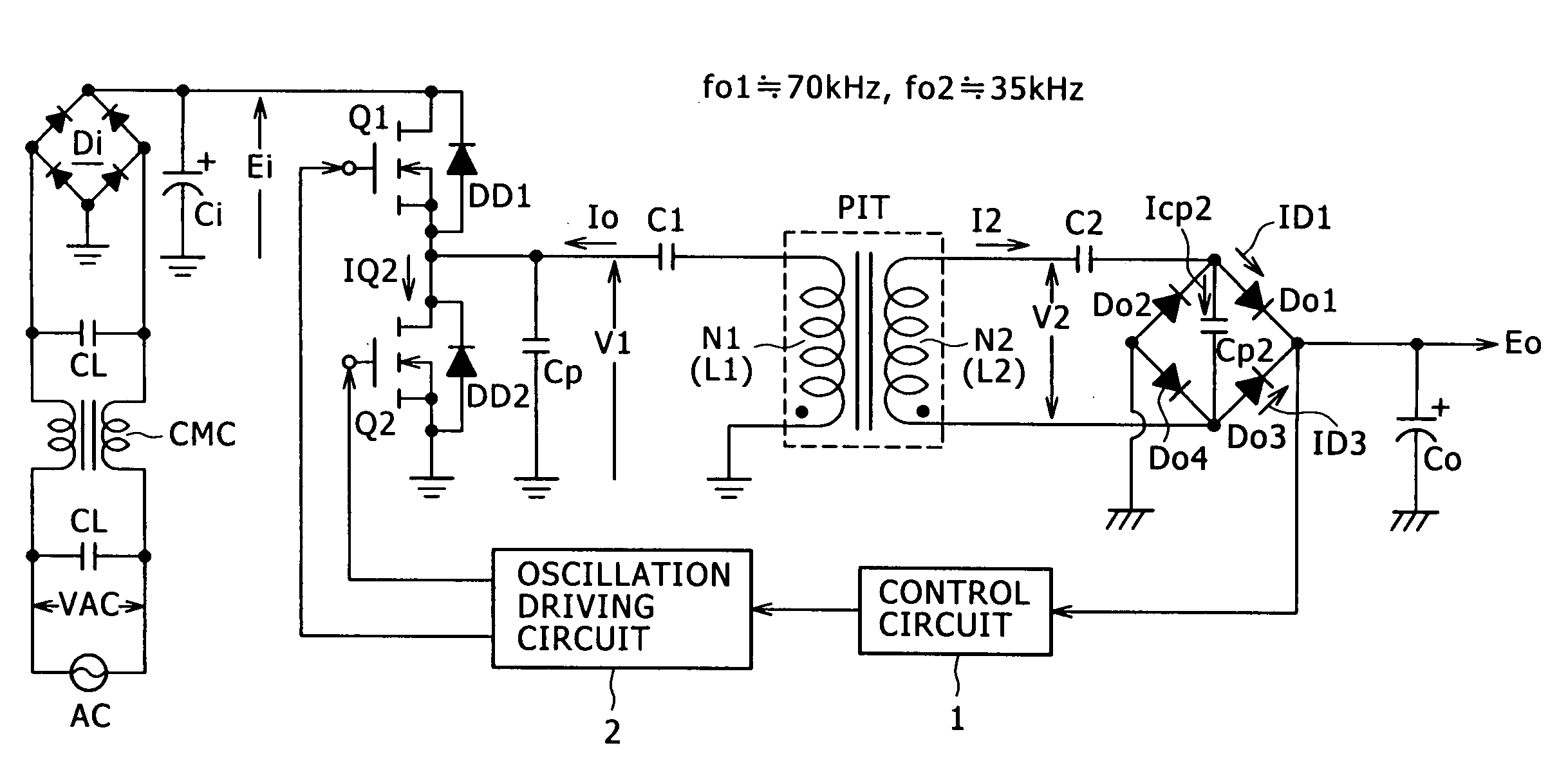
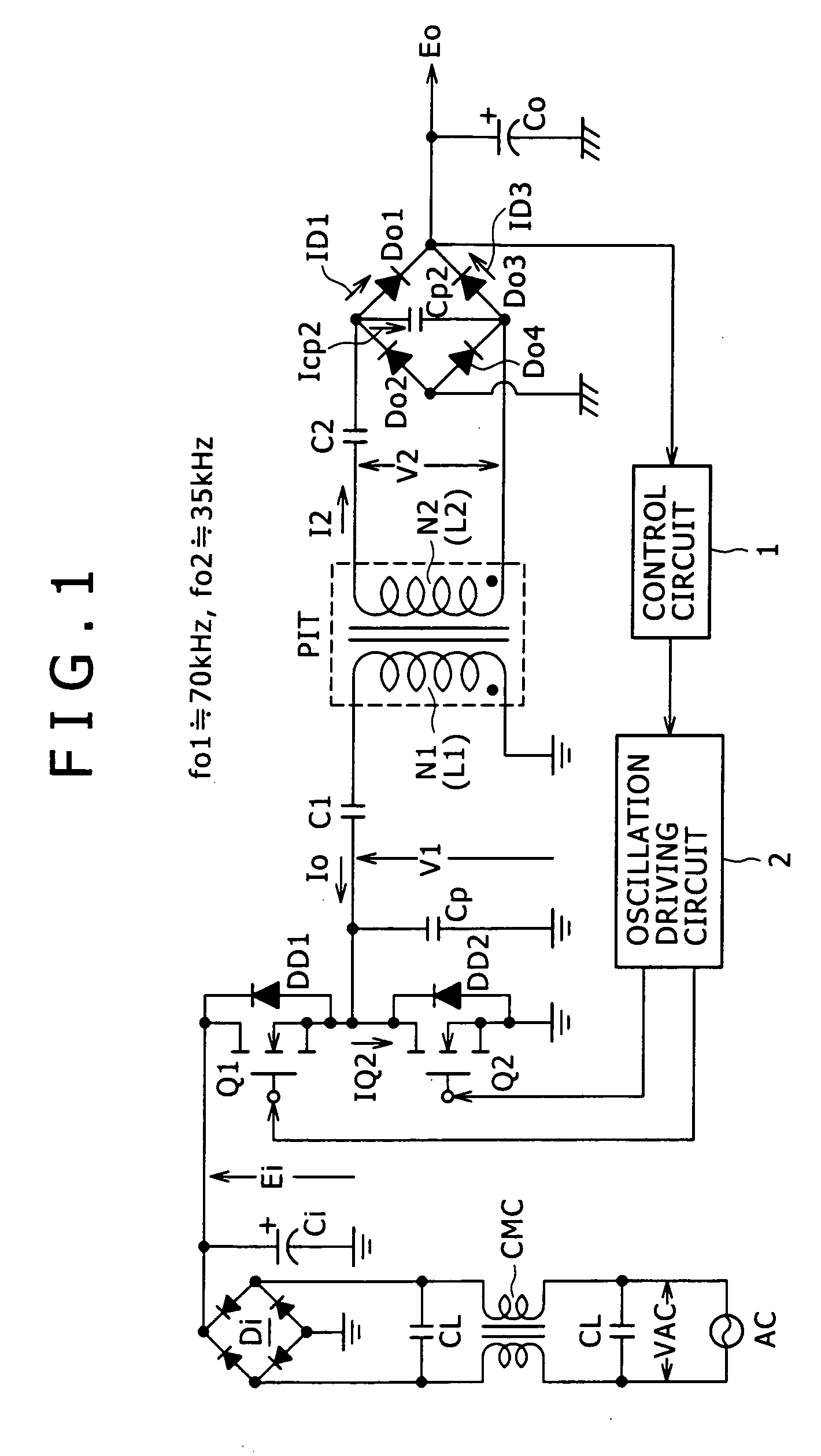
[0129]FIG. 1 shows an example of the configuration of a switching power supply circuit according to the present invention. Referring to FIG. 1, the power supply circuit is configured such that the basic configuration of the primary side thereof is a combination of a partial voltage resonance circuit with a separated excited current resonance type converter of a half-bridge coupling type.

[0130] Further, the power supply circuit of the first embodiment has a configuration ready for a wide range. The circuit operates in response to commercial AC power supplies of both the AC 100 V type and the AC 200 V type. Further, the power supply circuit is ready for a range of variation of the load power Po, for example, from Po=approximately 150 W (100 W or more) to Po=0 W (no load).

[0131] Furthermore, the power supply circuit is supposed to be used as a power supply, for example, of a printer apparatus and is configured so as to be ready for a load power Po from 150 W to 0 W.

[0132] First, in t...

second embodiment

[0264]FIG. 11 shows an example of the configuration of a power supply circuit according to the present invention.

[0265] The power supply circuit shown in FIG. 11 has a basic configuration as a multiple composite resonance type converter including a bridge full wave rectification circuit (Di, Ci) as a rectification circuit system for producing a rectification smoothed voltage Ei (DC input voltage) and adopts a half bridge coupling system for a primary side current resonance type converter similar to the power supply circuit described hereinabove with reference to FIG. 1.

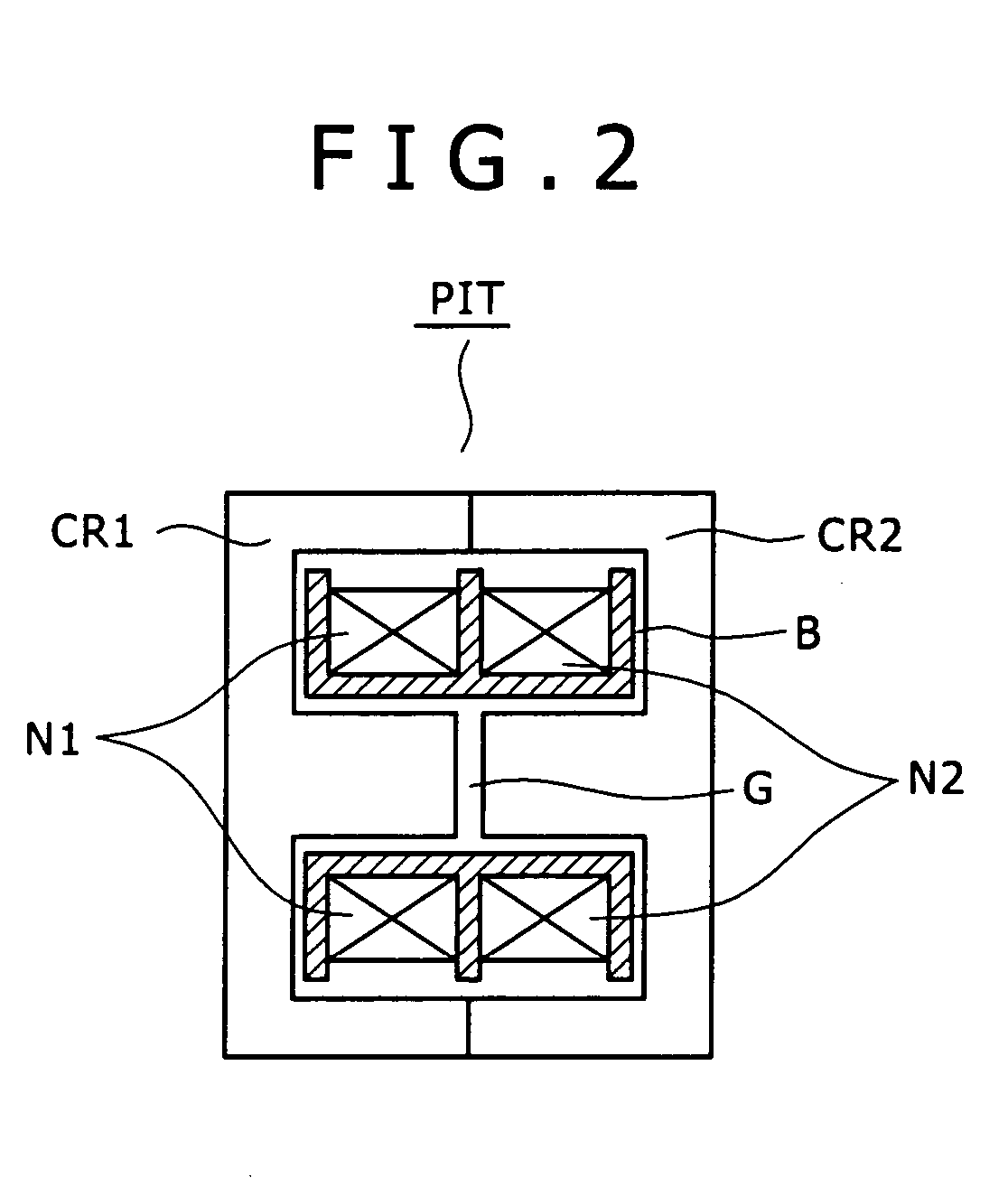
[0266] Further, in order to set the coupling coefficient k to k=approximately 0.65 or less, a gap length of approximately 2.8 mm is set for the gap G formed in the inner magnetic leg of an insulating converter transformer PIT having the structure, for example, shown in FIG. 2, in a manner similar to the power supply circuit of the first embodiment shown in FIG. 1.

[0267] Further, it is supposed that the present power...

third embodiment

[0325]FIG. 17 shows an example of the configuration of a power supply circuit according to the present invention.

[0326] The power supply circuit shown in FIG. 17 has a basic configuration as a multiple composite resonance type converter. The converter includes a bridge full wave rectification circuit (Di, Ci) as a rectification circuit system for producing a rectification smoothed voltage Ei (DC input voltage) and adopts a half bridge coupling system for a primary side current resonance type converter similar to the power supply circuits described hereinabove with reference to FIGS. 1 and 11.

[0327] Further, in order to set the coupling coefficient k to k=approximately 0.65 or less, a gap length of approximately 2.8 mm is set for the gap G formed in the inner magnetic leg of an insulating converter transformer PIT having the structure, for example, shown in FIG. 2.

[0328] Further, it is supposed that the present power supply circuit is incorporated as a power supply in, for example,...


PUM


Abstract

The present invention provides a power supply circuit performing constant voltage control by switching frequency control and achieving minimization of a necessary control range of the switching frequency control and implementation of a configuration ready for a wide range. A switching power supply circuit includes a switching circuit, a switching driving unit, an insulating converter transformer, a primary side series resonance circuit, a secondary side series resonance circuit, a secondary side DC output voltage production unit, a constant voltage control circuit, and a composite coupling coefficient setting mechanism.

Description

CROSS-REFERENCE TO RELATED APPLICATIONS [0001] The present application claims priority from Japanese Application Nos. 2004-162175 filed May 31, 2004, 2004-194105 filed Jun. 30, 2004, 2004-265441 filed Sep. 13, 2004, 2004-269828 filed Sep. 16, 2004, and 2005-054550 filed Feb. 28, 2005, the disclosures of which are hereby incorporated by reference herein. BACKGROUND OF THE INVENTION [0002] This invention relates to a switching power supply circuit to be used as a power supply for various electronic apparatus. [0003] Various power supply circuits having a resonance type converter on the primary side have been proposed by the assignee of the present application. One such power supply circuit is disclosed, for example, in Japanese Patent Laid-Open No. 2003-235259 (hereinafter referred to as Patent Document 1). [0004]FIG. 44 shows the switching power supply circuit disclosed in Patent Document 1 which includes a resonance type converter. Referring to FIG. 44, the power supply circuit show...

Claims


Application Information

Patent Timeline
IPC IPC(8): H02M3/338H02M3/335H02M3/337
CPCH02M3/3376H02M3/3385H02M2001/0058Y02B70/1491H02M1/0058Y02B70/10H02M3/28
Inventor YASUMURA, MASAYUKI
Owner SONY CORP
Why Eureka
Try Eureka