Method for path-seacher scheduling

a path-seacher and scheduling technology, applied in diversity/multi-antenna systems, digital transmission, polarisation/directional diversity, etc., can solve problems such as large power consumption, type of interference, and data uncertainty, and achieve the effect of reducing the power consumption of a mobile communication terminal operative and reducing the power consumption of a path-searcher

Active Publication Date: 2005-12-08
TELEFON AB LM ERICSSON (PUBL)
View PDF1 Cites 6 Cited by
  • Summary
  • Abstract
  • Description
  • Claims
  • Application Information

AI Technical Summary

Benefits of technology

[0011] The object of the invention is to provide a method for decreasing the power consumption of a mobile communication terminal operative in a telecommunication system. More precisely, the object of the invention is to provide a method for decreasing the power consumption of a path-searcher of a receiver of the mobile terminal. Also, it is an object of the invention to provide a method, with which it is possible to follow the movement of a power profile of a path-searcher.

Problems solved by technology

Multi-path interference is caused by the broadcast signal travelling over different paths to reach the receiver.
This results in two types of interference;
Inter-chip interference: The reflected signals are delayed long enough that successive chips in the demodulated signals overlap, creating uncertainty in the data.
Selective fading: The reflected signals are delayed long enough that they are randomly out of phase, and add destructively to the signal, causing it to fade.
The more frequent the path-searcher activations become, the larger the power consumption is going to be.
This is a problem as low power consumption is essential for a mobile terminal.
However, this requires that the fixed pattern is chosen according to the worst possible case, which could be a considerably waste of power consumption.
However, as the signal contains a lot of noise, the estimate of the speed of the terminal is not very robust, which makes it difficult to use said estimate to schedule the path-searcher activations.
Also, clock drift between the base station and the mobile terminal will not be found using the known prior art, causing a further degradation of the activations of the path-searcher.

Method used


Image

  • Method for path-seacher scheduling
  • Method for path-seacher scheduling
  • Method for path-seacher scheduling

Examples


first embodiment

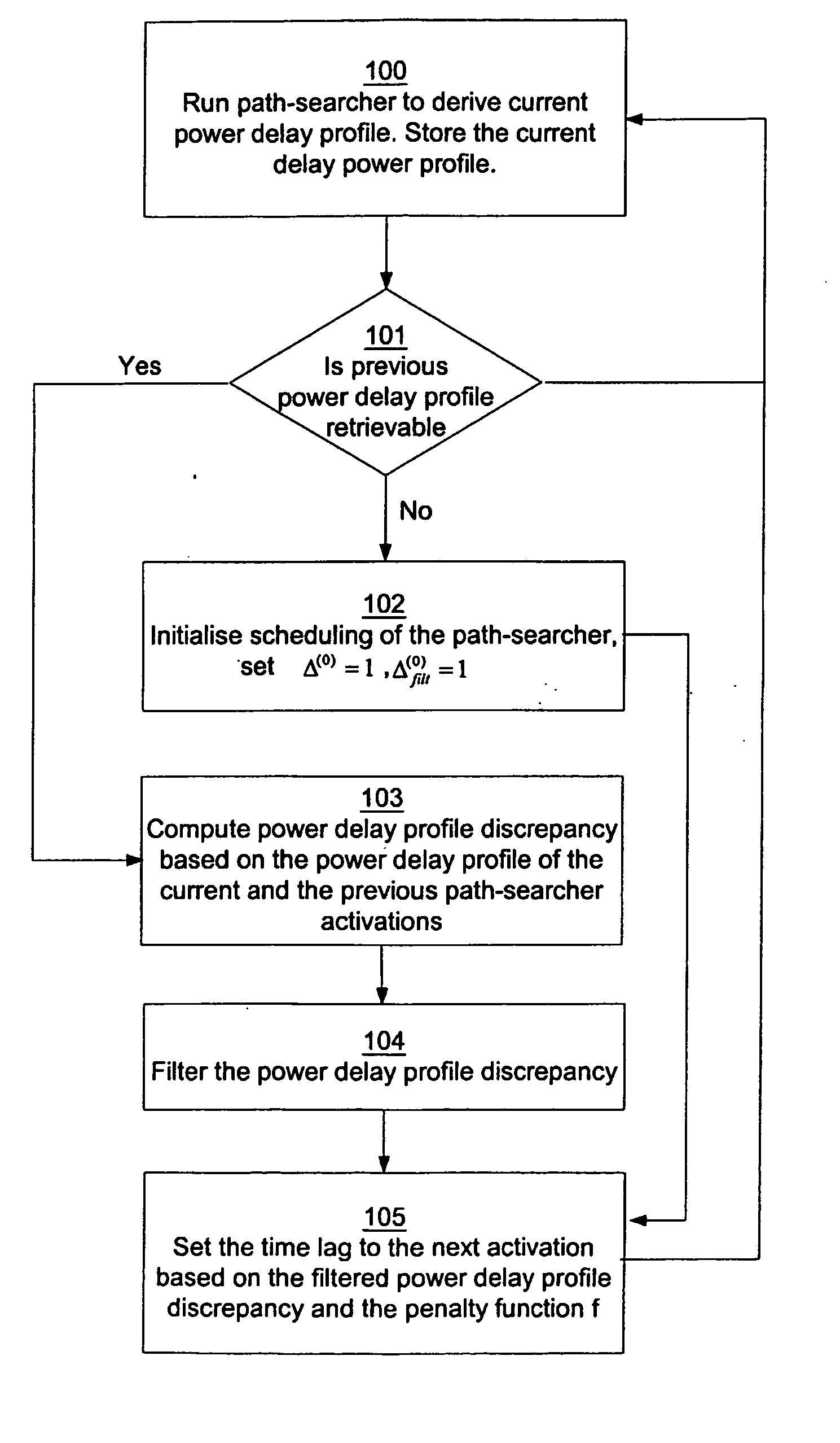
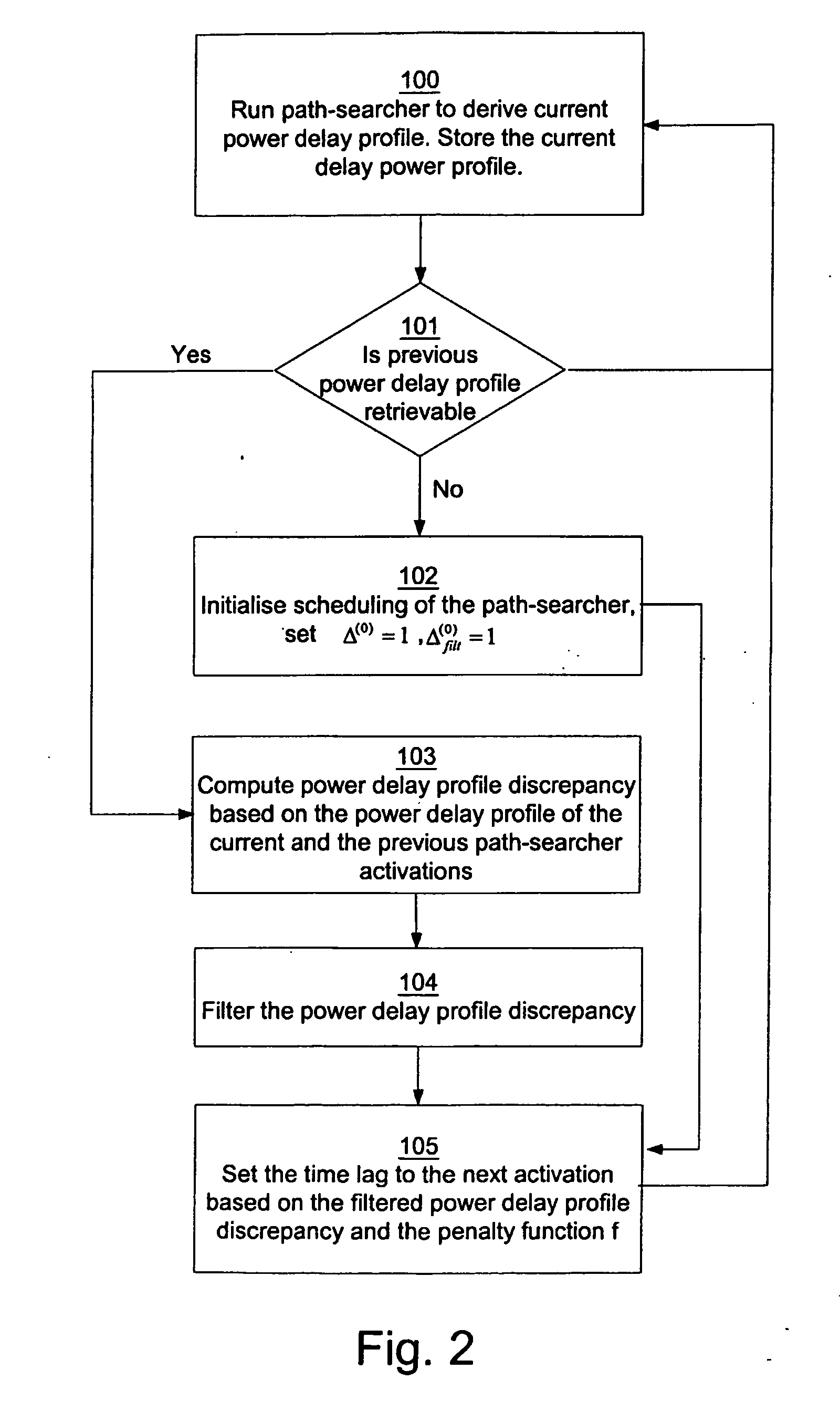
[0037] In a first embodiment, the current power delay profile is denoted by p(n), where n>=1, and the previous power delay profile p(n−1), each comprising a number of delay powers pi. Consequently, an estimate of the first power delay profile is denoted by p(0). The minimum and maximum time lag to the next path-searcher activation is denoted by τmin and τmax, respectively. Examples of values of these variables are τmin=70 ms and τmax=500 ms. However, the specific values of τmin and τmax may be set differently and have to be thoroughly tested and evaluated in each individual case. τ(n) is the size of the time lag to the next path-searcher activation, which is adaptable as set out above.

[0038] The first embodiment of the scheduling of activation of the path-searcher 11 will now be explained with reference to FIG. 2. In a first step 100, the current power delay profile is derived by the path-searcher 11 of the receiver 10. The current power delay profile is stored in the memory 12 to b...

second embodiment

[0046] A second embodiment will now be described, by which the invention is further improved in that the memory capacity required will be decreased.

[0047] In the second embodiment, only a subset of the powers pi of the derived power delay profile is selected and denoted by {circumflex over (p)}i, j=1, . . . , {circumflex over (N)}p for deriving a reduced power delay profile. In this embodiment, the delay powers are indexed by j and correspond to a particular index i in the first embodiment. The powers of the multi-path signals may e.g. be chosen as the {circumflex over (N)}p paths with the largest powers. Consequently, only the selected powers have to be stored in the memory 12 for the following processing for the scheduling of the path-searcher 11. As in the first embodiment, the selected powers are normalized for processing purposes, i.e.: ∑j=1N^p⁢p^j=1.

[0048] The steps of the method according to the second embodiment will now be described with reference to FIG. 4. Some of the va...

third embodiment

[0067] The penalty function is, as in the previous embodiments, an arbitrary function chosen depending on the specific path-searcher implementation. The function shown in FIG. 3 and explained above is one example of the function f also for the When the time lag τ(n) is computed in step 305, the scheduling is returned to step 300, where the path-searcher is activated with the computed time lag τ(n).

[0068] A fourth embodiment of the method according to the method of the invention will now be described with reference to FIG. 7. In the fourth embodiment; complete or reduced power delay profiles may be utilized. For convenience, this embodiment will be explained with reference to complete current and previous power delay profiles p(n) and p(n−1), respectively, as in the first embodiment. In a first step 401 the path-searcher 11 of the receiver 10 is run to derive the current power delay profile, which is stored in the memory 12 to be used as the previous delay power profile in a subsequ...


PUM


Abstract

The invention describes a method for adaptively scheduling activation of a path-searcher for a mobile terminal (1) operative in a telecommunication system. The mobile terminal (1) is capable of receiving multi-path signals (3, 4) originating from a scattered signal from a transmitter of at least one base station (2) in said system. The time lag between consecutive path-searcher activations is according to the method determined based on a value of the power delay profile discrepancy between two consecutive power delay profiles. The power delay profiles are derived from at least a subset of the powers of signals (3, 4) received at different delays during the path-searcher activation.

Description

FIELD OF THE INVENTION [0001] The present invention relates to a method for scheduling a path-searcher in a communication system, wherein signals are transmitted from a transmitter to a receiver. More specifically, the communication system comprises at least one base station and one mobile communication terminal, in which system signals comprise waveforms and wherein a received or preprocessed signal is sampled. According to the method of the invention mutual signal delays are utilized for scheduling of a path-searcher of the terminal. The signals originate from one or several transmitters, which signals have propagated along several different paths. [0002] The invention also relates to a mobile communication terminal adapted to adaptively schedule path-searcher activations depending on the discrepancy between power profiles of consecutive path-searcher activations. DESCRIPTION OF THE PRIOR ART [0003] In a telecommunication system, after a signal has left the transmitter it is scatt...

Claims


Application Information

Patent Timeline
Patent Type & Authority Applications(United States)
IPC IPC(8): H04B1/707
CPCH04B1/7113H04B1/7117
Inventor JONSSON, ELIAS
Owner TELEFON AB LM ERICSSON (PUBL)
Why Eureka
Try Eureka