Non-mechanical adjustment of an optical fiber to an optical output port

a technology of optical output port and optical fiber, which is applied in the direction of optics, instruments, optical light guides, etc., can solve the problems of low cost of epoxy attachment, inability to meet the requirements of high-precision attachments, and inability to maintain

Inactive Publication Date: 2005-12-08
PHC HLDG CORP
View PDF7 Cites 4 Cited by
  • Summary
  • Abstract
  • Description
  • Claims
  • Application Information

AI Technical Summary

Benefits of technology

[0006] The present invention is embodied in a method of aligning an optical fiber attached to a mount pad by a heat sensitive attachment to an adjacent optical source having an optical output port by activating the optical source to emit a signal from the optical output port, aligning a plurality of high-power lasers such that their respective beams are incident on the heat sensitive attachment, activating the plurality of

Problems solved by technology

The miniature dimensions of components used in modern optical communication systems render such alignment difficult both to achieve and to maintain.
For example, one problem in the construction of laser transmitters is that of efficiently coupling the optical output from a laser diode into an optical fiber.
Epoxy attachment is low cost but may have too much thermal expansion for high precision attachments.
Furthermore, it is not reliable over a long period of time due to outgassing and alignment shifts arising from aging and temperature cycling.
Laser weld techniques are reliable but require costly ferrulization of the fiber and specially designed mounts or clips to allow weld attachment of the ferrulized fiber.
The mounts/clips are expensive, large, and may creep over time.
However, existing solder attachment techniques tend to use either an integrated heating mechanism and/or a specially configured platform to isolate the heat for a solder reflow.
These tend to be expensive and undesirably large.
During the soldering process, the fiber mount may experience significant

Method used


Image

  • Non-mechanical adjustment of an optical fiber to an optical output port
  • Non-mechanical adjustment of an optical fiber to an optical output port
  • Non-mechanical adjustment of an optical fiber to an optical output port

Examples


Embodiment Construction

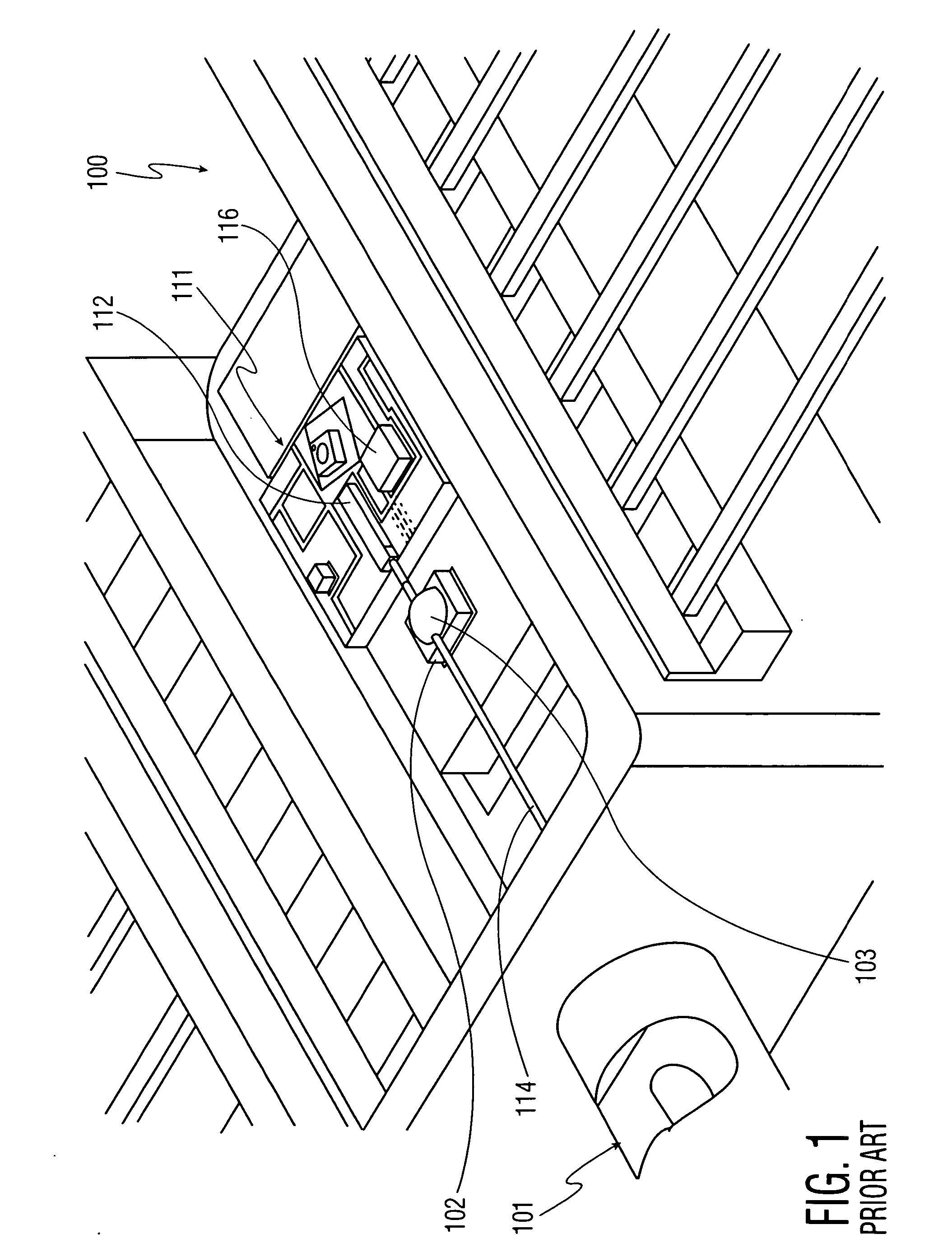
[0019] Referring now to the drawing, in which like reference numbers refer to like elements throughout the various figures that comprise the drawing, FIG. 1 shows a butterfly package 100 according to the prior art. The prior art package 100 includes optical fiber 114 inserted through snout feedthrough 101 and attached to fiber mount 102 with solder attachment 103. Optical fiber 114 is also optically coupled to optical component 112 (e.g. semiconductor laser, laser diode chip, photodetector) mounted on a substrate 111. Also included in the package shown in FIG. 1 is a thermistor 116. If the package includes a thermo-electric cooler (TEC) it is beneath the substrate 111.

[0020] It can be seen from FIG. 1 that optical fiber 114 is mounted on a fiber mount 102 that is separate from the substrate 111 on which optical component 112 is mounted. Furthermore, because the fiber is attached when the optical component 112 is in the package 100, the alignment process may be complicated because t...


PUM


Abstract

A method of adjusting the attachment of an optical fiber to a laser diode chip within a butterfly package, or any equivalent package, identifies the location of the solder attachment on the optical fiber, thereby moving one or more high power lasers so that their respective beams are incident on the solder attachment. Then, with the application of high power laser pulses according to a predetermined pulse schedule, the solder attachment is heated so that the optical fiber may shift vertically therein. By using an internal or external monitoring means such as an optical power meter, a determination is made when the optical alignment has reached a desired threshold such as when it exceeds a desired optical power output. The pulse schedule may be performed multiple times until a substantially optimized coupling is achieved for the final package.

Description

TECHNICAL FIELD [0001] The present invention relates generally to fiber-coupled optical assemblies and, more particularly, to a method of non-mechanically optimizing alignment of an optical fiber to an optical output port in a butterfly package. BACKGROUND OF THE INVENTION [0002] The importance of achieving accurate mutual alignment of individual components in any optical system is well known. The miniature dimensions of components used in modern optical communication systems render such alignment difficult both to achieve and to maintain. For example, one problem in the construction of laser transmitters is that of efficiently coupling the optical output from a laser diode into an optical fiber. To obtain efficient coupling, the fiber end is desirably precisely aligned with the emitting area of the laser. When such alignment is achieved, the fiber is then fixed in place, ideally by a method that ensures alignment is sustained throughout the device lifetime. [0003] Typically, fiber-...

Claims


Application Information

Patent Timeline
IPC IPC(8): G02B6/42G02B6/36G02B6/24
CPCG02B6/4225G02B6/4227
Inventor MASSEY, BRIAN
Owner PHC HLDG CORP
Why Eureka
Try Eureka