Rotary spindle for power tool and power tool incorporating such spindle

Inactive Publication Date: 2005-12-08
BLACK & DECKER INC
View PDF50 Cites 14 Cited by
  • Summary
  • Abstract
  • Description
  • Claims
  • Application Information

AI Technical Summary

Benefits of technology

[0021] This provides the advantage of minimising the extent to which the or each re

Problems solved by technology

This significantly increases the cost and difficulty of manufacturing the hammer drill.
Furthermore, when the hammer drill is repaired, the entire spindle generally needs to be replaced, even if only part of the spindle is damaged, which makes repair of the drill costly.
However, this arrangement suffers from the drawbacks that because the guide tube and tool socket are connected to each other by means of a press fit, the cooperating parts of the guide tu

Method used


Image

  • Rotary spindle for power tool and power tool incorporating such spindle
  • Rotary spindle for power tool and power tool incorporating such spindle
  • Rotary spindle for power tool and power tool incorporating such spindle

Examples


Embodiment Construction

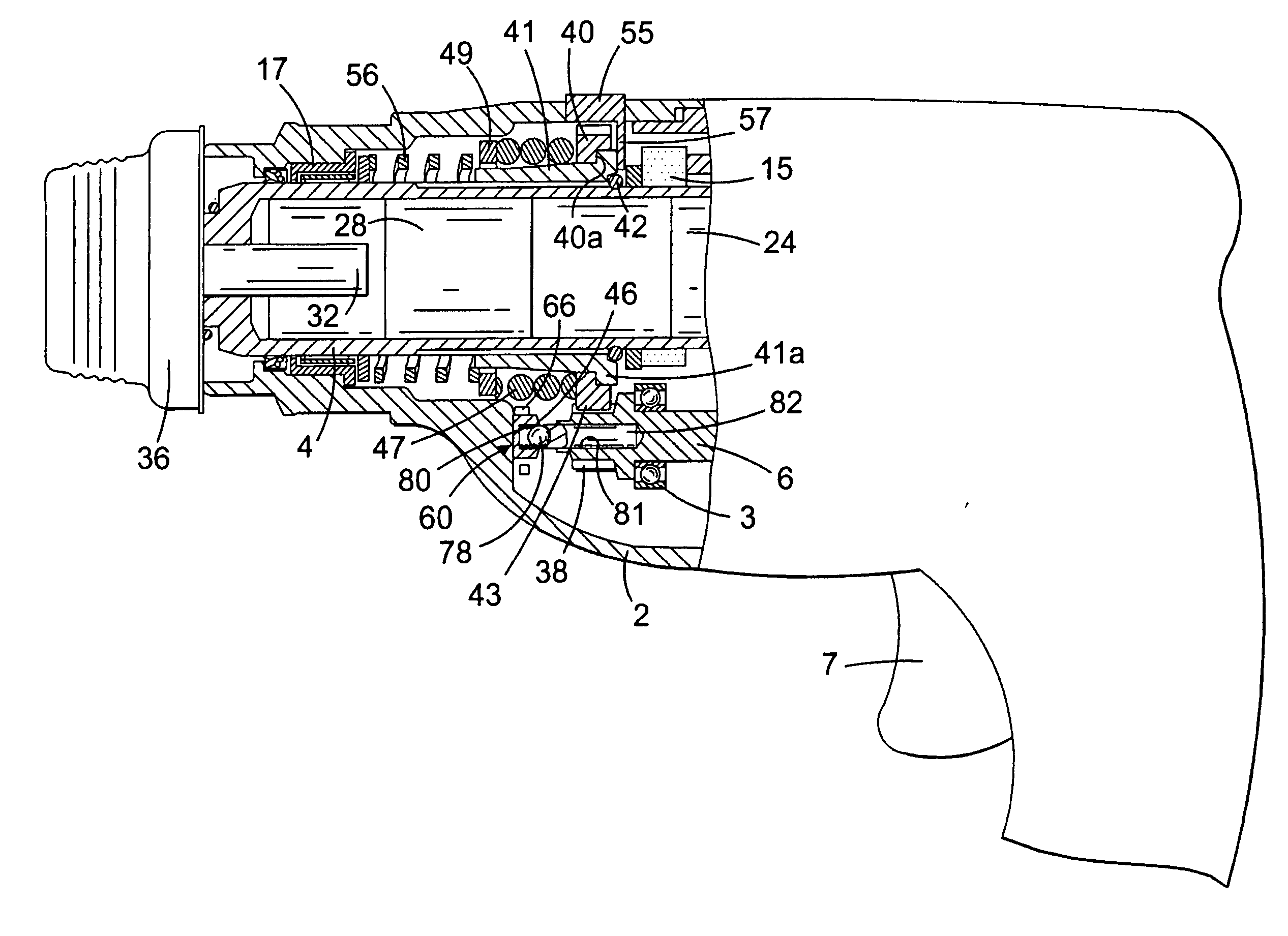
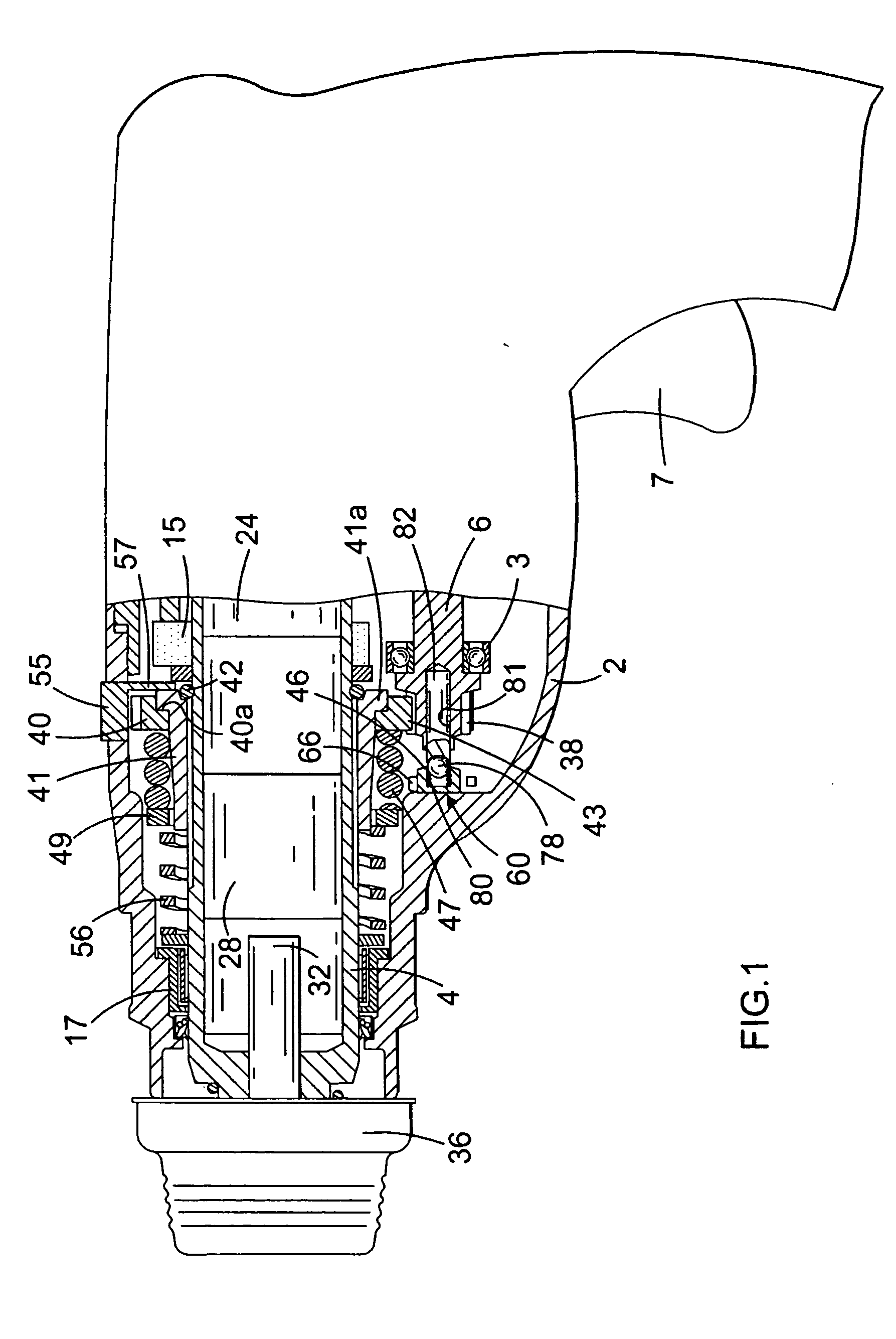
[0029] Referring to FIG. 1, a rotary hammer has a forward portion shown in cross-section, and a rear portion incorporating a motor and pistol grip rear handle in a conventional manner. Alternatively, the handle may be of the D handle type. The handle portion incorporates a trigger switch 7 for actuating an electric motor which carries a pinion (not shown) at the forward end of its armature shaft. The pinion of the motor rotatingly drives an intermediate shaft 6 via a gear which is press fit onto the rearward end of the intermediate shaft 6. The intermediate shaft 6 is rotatably mounted in a housing 2 of the hammer via a first bearing (not shown) located at the rearward end of the intermediate shaft 6 and a forward bearing 3 located at the forward end of the intermediate shaft 6.

[0030] A wobble drive hammering mechanism, of a type which will be familiar to persons skilled in the art, is provided for reciprocatingly driving a piston 24. The piston 24 is slidably located within a holl...


PUM

PropertyMeasurementUnit
Timeaaaaaaaaaa
Resilienceaaaaaaaaaa

Abstract

A rotary spindle 4 for a power tool such as a hammer drill is disclosed. The spindle 4 comprises a first spindle part 402 for rotation about its longitudinal an axis by means of a motor and having an inwardly directed rim 406, and a second spindle part 404 for supporting a drill bit of the hammer drill and having an outwardly directed rim 410. The second spindle part 404 extends through an aperture 408 in the first spindle part 402 and rims 406, 410 cooperate with each other to prevent removal of the second spindle part 404 from the first spindle part 402. A circlip 414 locks the first and second spindle parts 402, 404 together and maintains o-rings 412 under compression.

Description

FIELD OF THE INVENTION [0001] The present invention relates to rotary spindles for power tools, and relates particularly, but not exclusively, to rotary spindles for hammer drills. The invention also relates to power tools incorporating such spindles. BACKGROUND OF THE INVENTION [0002] Electrically driven hammer drills are known in which a motor causes a driving member in the form of a flying mass to be reciprocally driven in a hollow spindle by means of piston, while at the same time causing the piston to rotate about its longitudinal axis. The spindle supports a working member such as a drill bit, either by direct mounting of the drill bit to the spindle, or by supporting a tool holder which in turn supports the drill bit, such that rotation of the spindle about its axis causes rotation of the drill bit to effect a drilling action, while reciprocating movement of the flying mass within the spindle imparts hammer impacts to the drill bit. [0003] The spindle of a hammer drill of suc...

Claims


Application Information

Patent Timeline
IPC IPC(8): B25D17/06
CPCB25D17/06B25D2211/061Y10T409/309352
Inventor GENSMANN, STEFAN D.LAUTERWALD, MARTINBECHT, REIMUND
Owner BLACK & DECKER INC
Why Eureka
Try Eureka