
Silica glass containing TiO2 and process for its production

a technology of silicon glass and tio2 is applied in the field of silicon glass containing tio2, which can solve the problems of limited to about room temperature, and substantially zero coefficient of thermal expansion, and achieve excellent uniform mechanical characteristics and coefficients

Active Publication Date: 2005-12-08
ASAHI GLASS CO LTD
View PDF6 Cites 40 Cited by
  • Summary
  • Abstract
  • Description
  • Claims
  • Application Information

AI Technical Summary

Benefits of technology

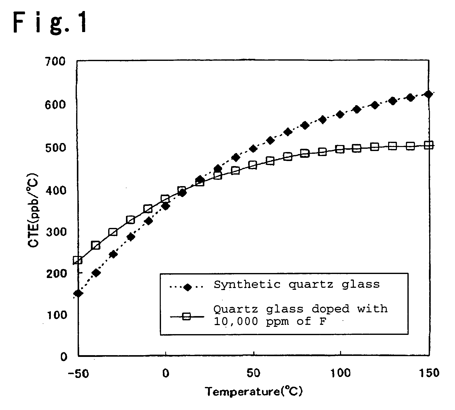
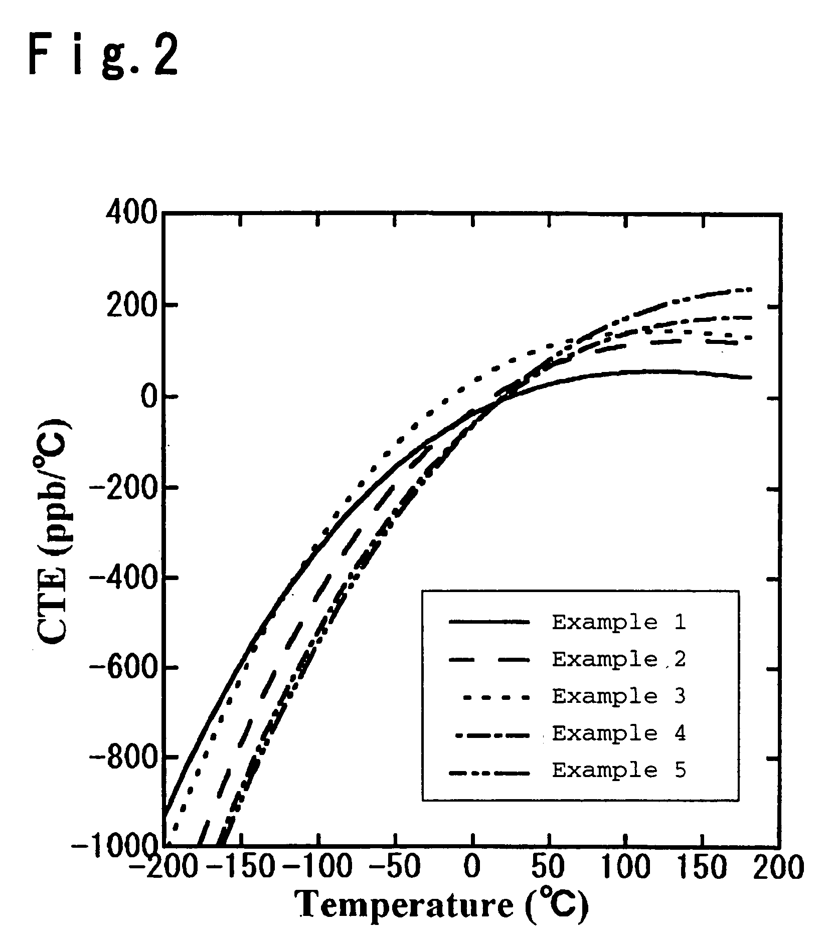
[0027] According to the present invention, it is possible to obtain a fluorine-containing TiO2—SiO2 glass having a small change in the coefficient of thermal expansion by temperature i.e. a wide temperature range where the coefficient of thermal expansion becomes to be substantially zero and being excellent in the uniformity of the mechanical characteristics and the coefficient of the thermal expansion in glass. Accordingly, it is very useful as a material for a component constituting an optical system to be used for EUVL.

Problems solved by technology

However, in the energy region of EUV light, there is no material to let the light pass therethrough.
However, in TiO2—SiO2 glass prepared by this method, the temperature region where the coefficient of thermal expansion becomes substantially zero, is limited to about room temperature.
However, with conventional TiO2—SiO2 glass, the temperature region where the coefficient of thermal expansion becomes substantially zero, is narrow, and such is inadequate to be used for an optical material for the exposure device for EUVL.

Method used


Image

  • Silica glass containing TiO2 and process for its production
  • Silica glass containing TiO2 and process for its production

Examples


example 1

[0074] TiO2—SiO2 glass particles obtained by gasifying TiCl4 and SiCl4 as glass-forming materials for TiO2—SiO2 glass, respectively, then mixing them and feeding them to heat hydrolysis (flame hydrolysis) in oxyhydrogen flame, were deposited and grown on a target to form a porous TiO2—SiO2 glass body having a diameter of about 80 mm and a length of about 100 mm (step (a)).

[0075] The obtained porous TiO2—SiO2 glass body was difficult to handle as it was, and as deposited on the target, it was maintained at 1,200° C. for 4 hours in atmospheric air and then removed from the target.

[0076] Thereafter, the porous TiO2—SiO2 glass body was set in an electric furnace capable of controlling the atmosphere, and after reducing the pressure to 10 Torr at room temperature, while introducing a gas mixture of He / SiF4=90 / 10 (volume ratio), it was maintained in this atmosphere at 1,000° C. under a normal pressure for 4 hours to carry out fluorine doping (step (b)).

[0077] Thereafter, it was maintai...

example 2

[0080] TiO2—SiO2 glass particles obtained by gasifying TiCl4 and SiCl4 as glass-forming materials for TiO2—SiO2 glass, respectively, then mixing them and feeding them to heat hydrolysis (flame hydrolysis) in oxyhydrogen flame, were deposited and grown on a target to form a porous TiO2—SiO2 glass body having a diameter of about 80 mm and a length of about 100 mm (step (a)).

[0081] The obtained porous TiO2—SiO2 glass body was difficult to handle as it was, and as deposited on the target, it was maintained at 1,200° C. for 4 hours in atmospheric air and then removed from the target.

[0082] Thereafter, the porous TiO2—SiO2 glass body was set in a chamber capable of controlling the atmosphere, and after reducing the pressure to 10 Torr at room temperature, a gas mixture of O2 / SiF4=90 / 10 (volume ratio) was introduced, and the glass body was held at room temperature under normal pressure for 24 hours to carry out fluorine doping (step (b)).

[0083] Thereafter, the F-containing porous TiO2—S...

example 3

[0086] ULE#7972 manufactured by Corning Inc., known as zero expansion TiO2—SiO2 glass, was held at 900° C. for 100 hours and then quenched to control the fictive temperature (step (e)).


PUM

PropertyMeasurementUnit
fictive temperatureaaaaaaaaaa
temperatureaaaaaaaaaa

Abstract

A silica glass containing TiO2, which has a fictive temperature of at most 1,200° C., a F concentration of at least 100 ppm and a coefficient of thermal expansion of 0±200 ppb / ° C. from 0 to 100° C. A process for producing a silica glass containing TiO2, which comprises a step of forming a porous glass body on a target quartz glass particles obtained by flame hydrolysis of glass-forming materials, a step of obtaining a fluorine-containing porous glass body, a step of obtaining a fluorine-containing vitrified glass body, a step of obtaining a fluorine-containing formed glass body and a step of carrying out annealing treatment.

Description

TECHNICAL FIELD [0001] The present invention relates to a silica glass containing TiO2 (hereinafter referred to as TiO2—SiO2 glass) and a process for its production. Particularly, it relates to TiO2—SiO2 glass to be used for an optical material for an exposure device to be used for EUV lithography and a process for its production. In the present invention, EUV (Extreme Ultra Violet) light means light having a waveband in a soft X-ray region or in a vacuum ultraviolet region and specifically means light having a wavelength of from 0.2 to 100 nm. BACKGROUND ART [0002] Heretofore, in photolithography, it is common to employ an exposure device to transfer a fine circuit pattern onto a wafer to produce an integrated circuit. Along with high integration and high functionality of integrated circuits, microsizing of integrated circuits has been progressing, and an exposure device is required to form an image of a circuit pattern on a wafer with a high resolution in a deep focal depth, where...

Claims


Application Information

Patent Timeline
Patent Type & Authority Applications(United States)
IPC IPC(8): C03B8/04C03B19/14C03B20/00C03B37/014C03C3/06C03C3/112C03C4/00G03F1/22G03F1/24H01L21/027
CPCC03B19/1415C03B19/1461C03B2201/12C03B2201/42C03C3/06C03C2201/12C03C2201/23C03C2201/42C03C2203/40C03C2203/54
Inventor IWAHASHI, YASUTOMIKOIKE, AKIO
Owner ASAHI GLASS CO LTD
Learn More