Implant assembly device

Active Publication Date: 2005-12-08
SYNTHES USA
View PDF24 Cites 16 Cited by
  • Summary
  • Abstract
  • Description
  • Claims
  • Application Information

AI Technical Summary

Benefits of technology

[0011] The implant insertion instruments may comprise a handle member for implantation of a first fixation implant (or a first portion of an implant), an arm member for guiding of a second fixation implant (or a second portion of the implant) into bone, a sleeve member for protection of soft tissue and for translational and rotational control of the second fixation implant, a nut member for engaging the sleeve member, and a drive shaft with coupling member for attachment to the second fixation implant and for driving the second fixation implant through the arm member and sleeve member into the fractured bone. The implant insertion instruments may also include a striking member to aid the surgeon in inserting the first fixation implant into the fractured bone. A measuring device that reduces measuring errors made by a user and a measuring device that determines implant length, diameter, and angle of insertion may also be included. These implant insertion instruments may have a bore runnin

Problems solved by technology

These fractures are typically debilitating and often require the patient to undergo surgery.
However, even when the treatment of the fracture does not call for a complicated procedure such as complete replacement, the proper setting of a fractured bone can still pose substantial challenges to even the most skilled orthopedic surgeon.
These difficulties include dealing with the shape and positioning of the bones or bone fragments when aligning the fracture and the accompanying complications regarding the proper placement of an orthopedic implant for supporting and holding the fracture in proper alignment until it heals.
This latter problem of implant alignment still remains as one of the challenges facing an orthopedic surgeon in fracture surgery.
However, the size and shape of the IM rod can make its insertion into the medullary canal difficult.
As the IM rod may be smooth and may have a narrow diameter, the surgeon may not be able to achieve a tight grip on the rod in surgery.
Furthermore, a large amount of force may be needed to push the rod into the medullar

Method used


Image

  • Implant assembly device
  • Implant assembly device
  • Implant assembly device

Examples


Embodiment Construction

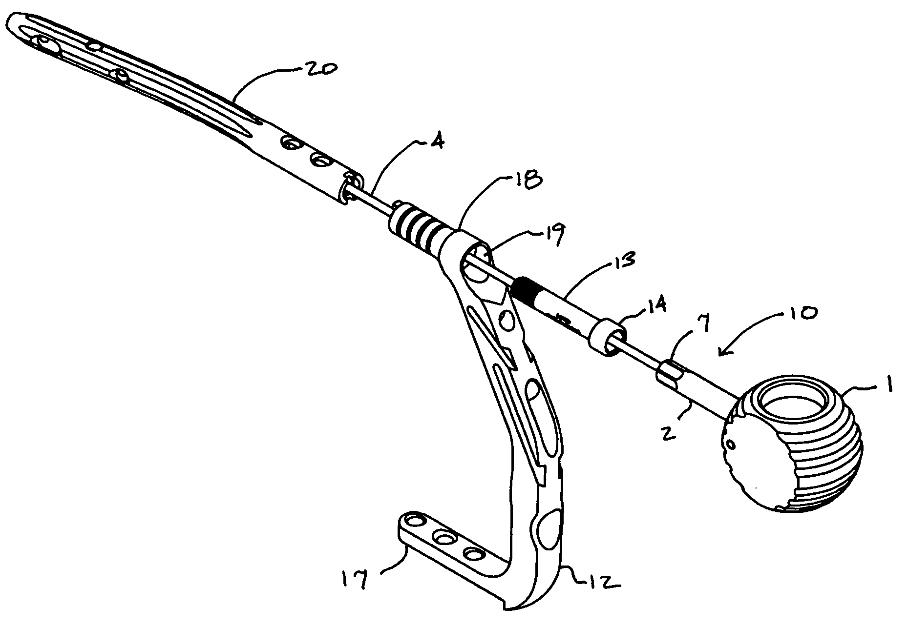
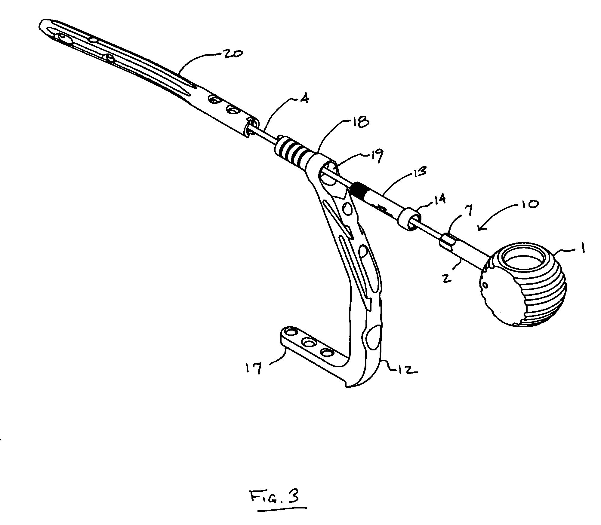
[0020]FIG. 3 shows the preferred embodiment of the implant assembly device 10, along with an IM rod 20 and various components that may be associated with the insertion of an IM rod. FIG. 3 shows a connecting screw 13 and an insertion handle 12 in a partially assembled configuration as each is placed on the device 10 prior to being locked into position on the IM rod 20.

[0021] As illustrated in FIGS. 1 and 2, handle 1 is preferably connected to a shaft 2 that extends from the body of handle 1. The handle 1 preferably is of an appropriate size and shape to be easily gripped by a user and to allow the user to apply a rotational force to the device. While the handle is shown in a generally spherical configuration, the handle may also be of any shape that preferably allows the user to grip the device. The handle may be provided with grooves or other form of surface irregularities or texturing to improve the gripping qualities of the handle. The handle may alternatively be provided with a...


PUM


Abstract

This invention relates generally to systems for the internal fixation of bone fractures, and particularly, to equipment associated with the insertion of intramedullary fracture fixation devices such as those used in the treatment of long bone fractures, such as for example fractures of the femur, tibia, humerus, etc. An implant assembly device of the present invention may comprise a handle, a shaft with a first end and a second end, and an elongated rod extending from the shaft. The first end of the shaft is connected to the handle and the second end of the shaft is configured to engage the head of a connecting screw. The device can be held with one hand while the various components are placed one by one into their proper position onto the rod, leaving the other hand free to manipulate the other components.

Description

FIELD OF THE INVENTION [0001] This invention relates generally to systems for the internal fixation of bone fractures, and particularly, to equipment associated with the insertion of intramedullary fracture fixation devices such as those used in the treatment of long bone fractures, such as for example fractures of the femur, tibia, humerus, etc. BACKGROUND OF THE INVENTION [0002] Skeletal fractures are common injuries. These fractures are typically debilitating and often require the patient to undergo surgery. Depending on the severity of the fracture, the orthopedic surgeon has several options for treatment, ranging from simple fracture reducing implants to complete prosthetic replacements. However, even when the treatment of the fracture does not call for a complicated procedure such as complete replacement, the proper setting of a fractured bone can still pose substantial challenges to even the most skilled orthopedic surgeon. [0003] The difficulties that a surgeon has to deal w...

Claims


Application Information

Patent Timeline
IPC IPC(8): A61B17/22A61B17/72A61B17/88
CPCA61B17/72A61B17/921
Inventor POWELL, SEANPATEL, DIPAN
Owner SYNTHES USA
Why Eureka
Try Eureka