
Process for protecting a robot from collisions

a robot and process technology, applied in the field of process for protecting a robot from collisions, can solve the problems of robot damage, flange tool, transport system or other peripheral components, semaphore access taking place via data lines, and failure to offer the security of semaphore, so as to achieve the effect of reliable protection from collisions

Inactive Publication Date: 2005-12-08
KUKA ROBOTER
View PDF7 Cites 77 Cited by
  • Summary
  • Abstract
  • Description
  • Claims
  • Application Information

AI Technical Summary

Benefits of technology

[0014] The basic object of the present invention is to provide a process with which at least one robot can be reliably protected from collisions especially with other robots.
[0016] Consequently, the present invention contains an off-line analysis of the participating robot programs on the basis of which the robot programs are modified, if necessary, by inserting interlocks. The check for collisions—for programming sentences—takes place for sentences (“unit operating commands”) off-line, i.e., before the start of the robot programs for all possible combinations of sentences on the participating robots. Consequently, points in the program or sentence numbers at which interlock statements are to be inserted into the program are determined according to the present invention. This off-line processing may contain models with a high degree of detail, because no real time requirement is imposed on this processing step. Internal intermediate results of this check for collisions can be stored within the framework of the present invention, as a result of which it is possible, e.g., reteach only a few points, for which little computation time is needed. The result of the check for collisions is inserted in the program via interlock statements, i.e., the programs are expanded. Checking for “waiting necessary” is not coupled to movement commands, but is an independent statement of the robot program. However, cycle time is gained as a decisive advantage due to the finer check for collisions.
[0021] 3. Interlocks are separate program statements independently from movement commands. Interlock commands trigger communication between the participating controls for the exchange of semaphore variables. However, there is no implicit communication in case of movement commands according to the present invention for exchanging geometric information, i.e., there is no time delay in movement commands.
[0026] According to another preferred embodiment of the process, provisions are made that bounding volumes of the at least one robot or robot parts, which are checked for collisions, are generated for the collision recognition, and the hierarchies of such bounding volumes, which can be generated especially with any desired high degree of detail, are generated in the known manner in a preferred variant. A hierarchy of bounding volumes is used to reduce the average effort for a collision check between two objects. The hierarchy comprises here simply structured bodies, which surround the entire geometry of the original object, and even the convex volume of that object. The bounding volumes can be transformed, on average, more rapidly to the current position and checked for collision than the exact geometry of the corresponding objects. The use of bounding objects to rapidly rule out collisions is a suitable method of approximately achieving real time capability. Possible bounding volumes are spheres, axis-oriented boxes (AABB), oriented boxes (OBB) and convex volumes as well as optionally additional geometric bounding volumes. The bounding volumes are generated mostly off-line and are arranged in an ascending order according to their accuracy of approximation. An exception is AABBs, which is generated by the system anew after each movement of the object on the basis of a “local” OBB. The ratio of the volume of the bounding volume to the volume of the underlying object is used as the heuristics for the degree of approximation. If different types of bounding volumes have a similar degree of approximation, the bounding volumes with the more time-consuming collision check are discarded. The topmost level of the hierarchy and consequently the most accurate representation of an object is formed by the convex volume of the object. Various program packages can be used for the collision recognition and for calculating the distance between convex volumes. As long as the bounding volumes of the two objects collide, the hierarchies are run through up to the checking of the convex volumes against one another. If these intersect as well, the collision recognition sends back “collide.”
[0029] Another preferred embodiment of the process according to the present invention provides for merging consecutive determined interlocks with one another in order to keep the number of interlocks low and to reduce the communication effort as a result.

Problems solved by technology

This will then lead to a collision and to damage to the robot, flange tool, transport system or other peripheral components.
The additional problem that the semaphore access takes place via data lines arises in distributed systems, such as robot controls.
However, this fails to offer the security offered by semaphores, because the two operations “checking whether a variable has been set and optionally setting it” can usually be interrupted.
There is a possibility of collision not only with the robot hand or the tool being carried by the robot.
If the programmer forgets about an interlock, deletes it by mistake or disregards it in another way, this may lead to a collision.
Costly disturbances may thus arise especially during the phase of start-up of a production cell / plant.
However, unrecognized collision potentials also lead to collisions in a non-producing plant because of the asynchronous movement process when a critical constellation accidentally develops for the first time and the necessary interlock is missing.
This is not always simple in practice.
On the one hand, this prospective view cannot be embodied in a robot system in a simple manner, and the brake path, which depends on the kinetic energy, does not allow a constant prospective path, either.
On the other hand, a real time-capable collision monitoring of a plurality of complex objects can hardly be achieved for reasons related to real time and memory reasons.
The main drawback is, however, that collision potentials are recognized only when a possible collision occurs and this leads to stopping of the robot.
Besides the problem of the above-described prospective approach and the real time capability, which likewise apply now, the requirements are not met satisfactorily in case of working areas used jointly.
The automatic planning of a collision-free path cannot lead to a satisfactory solution here.
The user's knowledge about the correct / optimal stop of the waiting robot and the knowledge about the sequence of machining by the robots in the joint working area cannot be satisfactorily implemented now because of the given complexity.
The generation of optimal collision-free paths that is suitable for practice and the automatic setting of optimal stops and movement sequences (sequence of the use of common working areas) is therefore still impossible now in case of complex machining cells with robots and transfer systems.

Method used


Image

  • Process for protecting a robot from collisions
  • Process for protecting a robot from collisions
  • Process for protecting a robot from collisions

Examples


Embodiment Construction

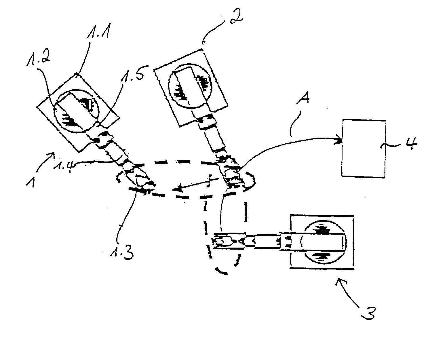
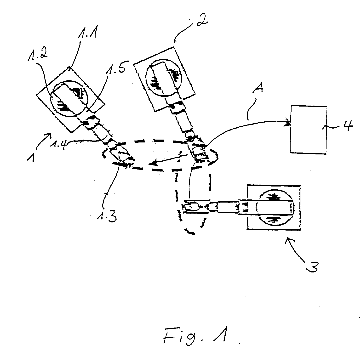
[0039] Referring to the drawings in particular, FIG. 1 shows a robot cell with three cooperating robots 1, 2, 3. The individual parts socket 1.1, carrousel 1.2, rocker 1.3, robot arm 1.4 and robot hand with tool 1.5 are designated in robot 1. The other robots 2, 3 have a corresponding design. The robots are arranged such and operate such that there are collision areas, which are schematically indicated by broken lines in FIG. 1. For example, a collision would occur between robot 3 and robot 2 in the shown position of robot 2 if robot 3 moved from its position, which is likewise shown, into the position shown for depositing a part 4 corresponding to arrow A.

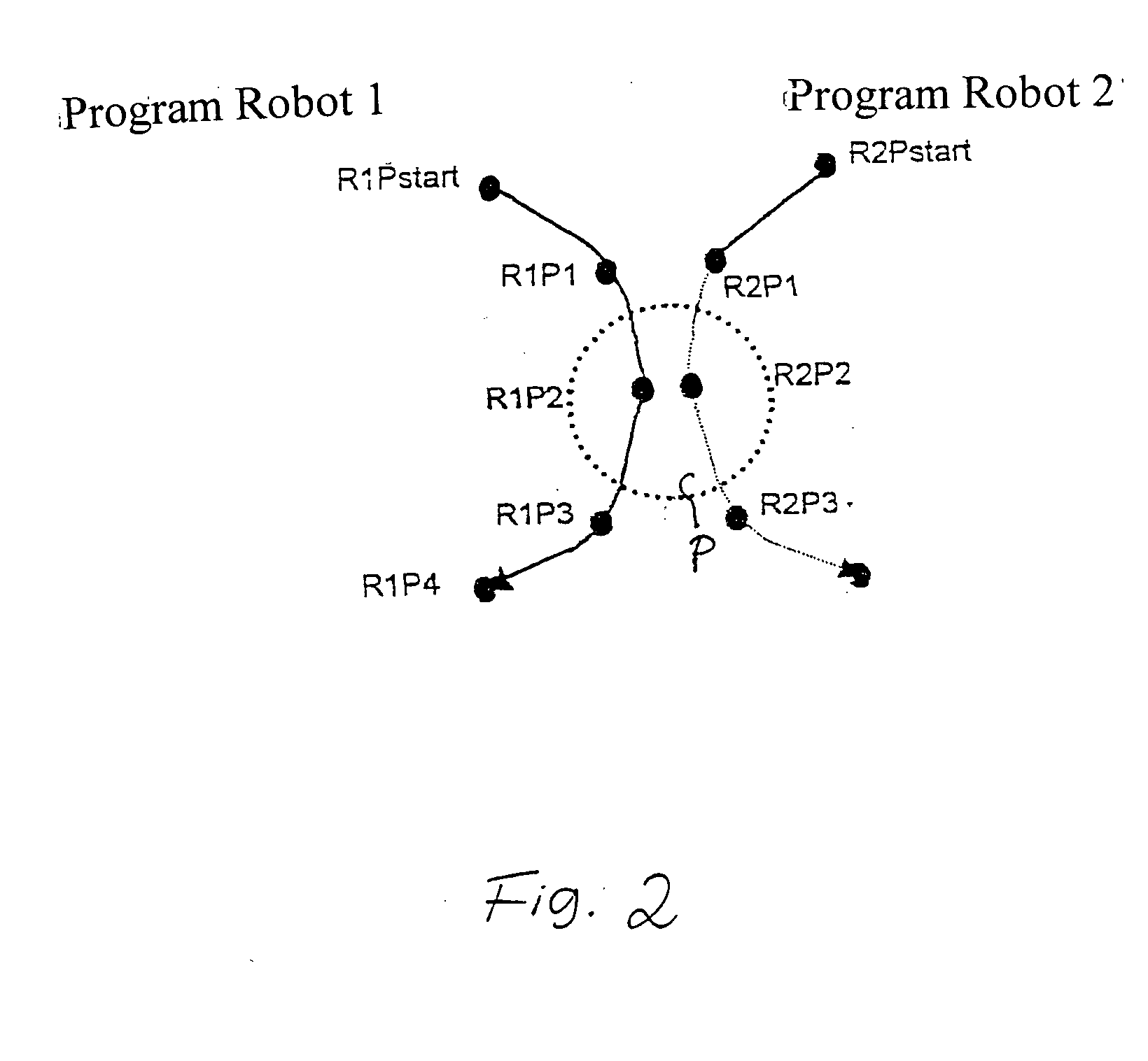
[0040] To prevent such a collision, interlocks are set and released, as they are shown in FIG. 2.

[0041] A working area used jointly, in which a collision could occur, is indicated by dotted lines here. For example, a robot 1 starts from its starting point R1Pstart and moves to a point R1P1 before the collision area P. By means o...


PUM


Abstract

A process for protecting at least two robots is provided, especially multiaxial industrial robots, from collisions, in which movements of a robot are automatically checked for possible collisions. Interlocks are automatically inserted in the movement process.

Description

CROSS REFERENCE TO RELATED APPLICATIONS [0001] This application claims the benefit of priority under 35 U.S.C. §119 of German Application DE 10 2004 027944.6 filed Jun. 8, 2004, the entire contents of which are incorporated herein by reference. FIELD OF THE INVENTION [0002] The present invention pertains to a process for protecting at least one robot, especially at least one multiaxial industrial robot, from collisions. BACKGROUND OF THE INVENTION [0003] Asynchronous movement processes of the robots and other mobile objects due to non-synchronized feed and removal of materials (insertion station, shuttle, intermediate buffering filling level, different machining times, etc.) are not avoidable within a production cell and they are mostly optimal concerning the machining time. To comply with preset joining sequences, processes also must, moreover, be carried out sequentially. If an application or a process requires machining by a plurality of robots, auxiliary axes or transport system...

Claims


Application Information

Patent Timeline
IPC IPC(8): B25J9/16
CPCB25J9/1666G05B19/4061G05B2219/36468G05B2219/40492G05B2219/39135G05B2219/40317G05B2219/40442G05B2219/39099
Inventor HIETMANN, GERHARDWEISS, MARTIN
Owner KUKA ROBOTER
Learn More